Saturday 22 February 2014

Interface Bench Test - Part 4

This morning, I decided instead of using HyperTerminal, or the Ardunio IDE Serial Monitor to interact with the Armdroid, I thought it would be good idea to develop a dedicated Windows application:


This is a fairly simple test application, but it should be good enough for anybody to test their Armdroid from any Windows based PC using Serial/USB connectivity.   I think you'll agree, this is a lot more user-friendly than what was shown in my last update.

You have to select which port your Armdroid is connected too.  Once connected, you can choose the motor channel, and step the motor any number of times:


Feedback from the controller is displayed in the output panel :


The application was developed in Visual Studio 2012 using the Microsoft .NET Framework.

Later, I'll be publishing my Armdroid Control Protocol specification Version 1.0, just as soon as I've finished my initial development work.

I'm going to standardize all my development activities around this protocol, and by doing so, we can have IBM PCs talking to Arduino or Raspberry Pi hosted Armdroid controllers, and more....   This platform independence will allow us to support many combinations of hosts/controllers in future.   Hopefully other readers/developers might adopt the same standard, and we'll see more Armdroid applications appear in time.

This can be downloaded from the software section - Windows Tools

Thursday 20 February 2014

Interface Bench Test - Part 3

I thought it would be a good idea to check through my program code on paper, checking the stepper motor sequencing is ready, and guess what....   I discovered a few bugs design limitations which had to be resolved before commencing the test.


To confirm the Arduino/Armdroid interface wiring used, the following connections have been made:

ARDUINO PIN
FUNCTION
ARMDROID PIN
2
D1
4
3
D2
3
4
D3
6
5
D4
5
6
D5
8
7
D6
7
8
D7
10
9
D8
9

The common grounds have been connected together - that's Pin 2 on the Armdroid interface, connected to any of the Ardunio's GND power pins.


Normally, I have some good news, and bad news.....  But, in this case, it's only good news to report....

The interface board is working faultlessly.

Motor addressing worked as expected for this generation of interface board.   I checked every motor channel, making sure the motor spins clockwise/counter-clockwise.   I also made certain that selecting a motor channel, doesn't inadvertently activate another motor channel.  I couldn't actually be happier with the results of my bench test!


If your wondering how this was done....   In my last post, I mentioned the Ardunio will be responding to commands sent via the Serial Port.   I have designed a simple communications protocol, which is the backbone to this.

The following functions have currently been implemented:
  • Select a motor channel
  • Drive a motor with a specified number of steps
  • Set the motor speed in RPM
  • Write a value directly to the Armdroid interface port


This is a screen shot of the Serial Monitor showing the waveform outputs (in binary) in use when pulsing the stepper motor on channel six :


This level of tracing proved to be invaluable for diagnosing a few other issues in the software.   This certainly helps to visualize whats happening on the Armdroid interface.

I intend to develop this protocol further to support driving multiple motors (necessary for pitching/rolling the gripper) and tracking motor offsets counters which can be used to return the arm to a predefined home position.


The source code will be published shortly.   I'm currently moving all my source code into a new GitHub Repository, so please check back later.....

Saturday 15 February 2014

Interface Bench Test - Part 2

I should have titled this Déjà vu

Last night turned into a fairly intensive evening of tracing the entire interface circuitry....  I did this not once, but twice!


I started by tracing the pinouts of the interface cable, confirming these match the literature, and what has been document elsewhere on the internet.

One problem I've found with the original documentation, it's not very clear illustrating these pin assignments, so I've put together the following table which might help:


PIN
ARMDROID FUNCTION
INPUT BITS
OUTPUT BITS
1
+5 V


2
GND


3
D2
N/C
A1
4
D1 (STROBE)
HIGH
LOW
5
D4
MS2
A3
6
D3
MS1
A2
7
D6
MS4
D2
8
D5
MS3
D1
9
D8
MS6
D4
10
D7
MS5
D3


The physical wiring is very different to prototype models.
At this point, I wanted to double check the address decoding of motor selections.

This has been the subject of great confusion, not only to myself, but other readers too.   My prototype variant turned out to have A1 as the most significant address bit, not A3 as expected.   It  seemed odd why this was the case, and without finding any examples of source code on the internet, it turned into one of those little mysteries of life.

Tracing this part of the circuit however resulted in a bit of a discovery....

Address bits A3 and A1 have been swapped, which means the address decoding for this generation of interface board is completely different to prototype variants.

My tracing determined:
D2 (exiting pin 8 from IC2C) feeds into Pin 1 (A) of the Demultiplexer (74LS138 / IC6)
D3 (exiting pin 6 from IC2B) feeds into Pin 2 (B)                  "
D4 (exiting pin 3 from IC2A) feeds into Pin 3 (C)                  "

Hopefully, any reader who previously read my post "Motor Addressing Solved" will understand that only applies to the address decoding of prototype variants only.   I would imagine, all later generations follow the above form of addressing logic.

I wonder if Colne made a mistake in the PCB routing of early prototype models, and subsequently corrected things?

To complicate matters, some of the schematics contain minor mistakes.  In time, I will redraw these for both generations of circuit boards, and make them available on this site.

I've previously spoken about my intention to develop a software library, and of course, this will need to support both addressing modes.   From a higher level view, any software consuming this library need not actually be concerned with these implementation details, we just need to config it correctly, and the library will do all the hard work.


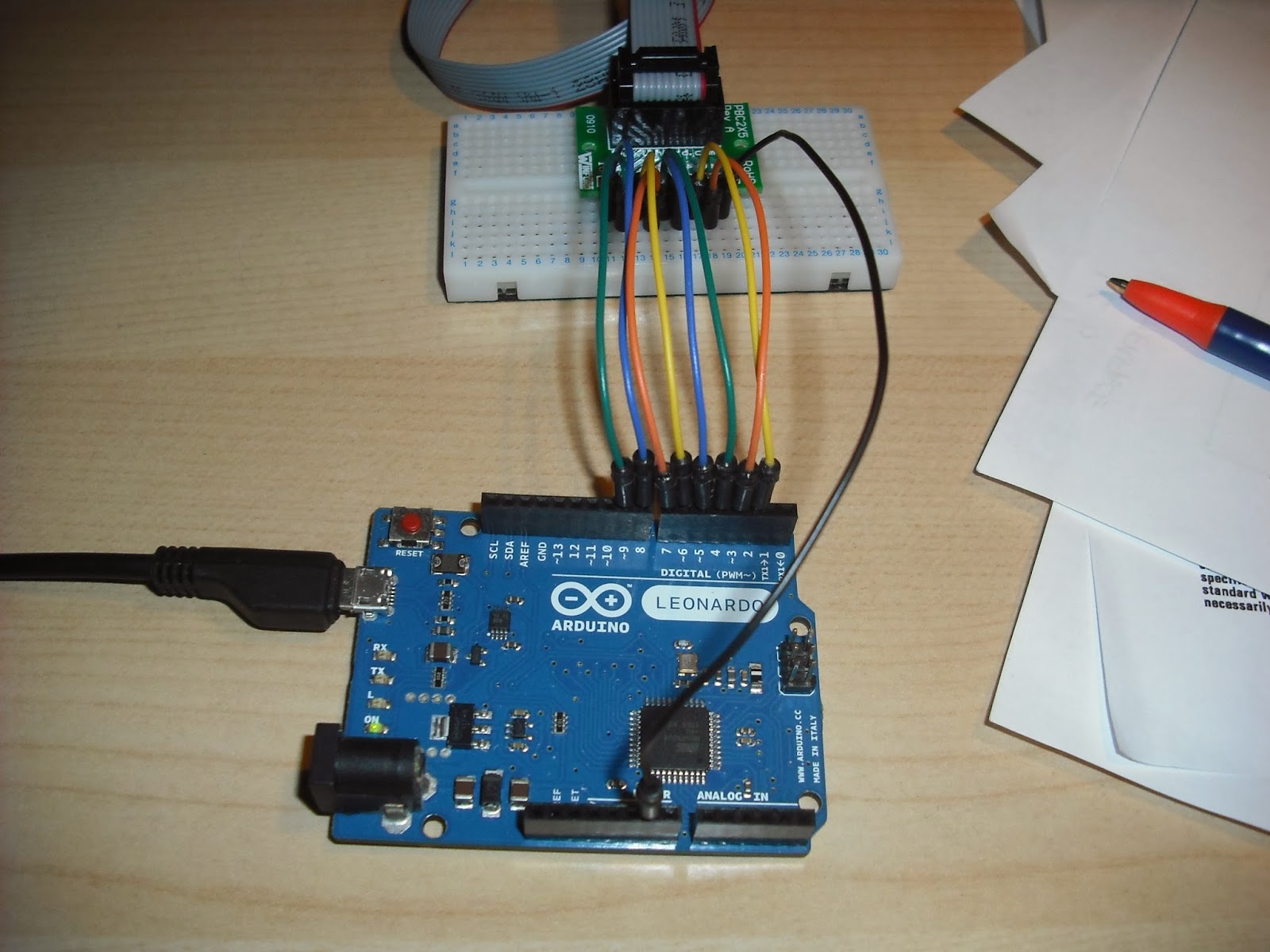
Anyway, with the pinouts confirmed, I am now wiring up my Arduino with a higher degree of confidence something might actually work:


Output pins 2 - 9 have been wired to correspond to bits D1 - D8, and the switching is all done in hardware.  This keeps things logically consistent with my existing Raspberry Pi interface, and that means program code should port relatively easily between the two devices.

Pins 0 (RX) and 1 (TX) have purposely been left unconnected, this is necessary when using serial communication.   My test program will be responding to commands sent via USB/Serial, this is why I have chosen to use the above pin assignments.

The +5 V line is not used, and common grounds have been connected together.  The Arduino Leonardo is a native 5V device, therefore no voltage conversion is necessary.

I'm currently making final edits to my program code, and then we're ready for the ultimate test this weekend....

Thursday 13 February 2014

Interface Bench Test - Part 1

My general plan for testing this interface is to perform a complete bench test outside of the Armdroid enclosure.

Only when I'm happy with everything, will I remove my existing circuit board and make the changes necessary to accommodate either circuit in future.

The picture on the right shows the circuit board remounted on the base plate to help protect everything whilst testing.


My initial inspection check-list included:
  • Check the board for dry joints and re-solder any found
  • Visual inspection - looking for signs of burnt-out components etc.
  • Held the board under a strong light and checked the underside to ensure there no solder bridges between the tracks (as per the instruction manual)

Power Connection

Colne Robotics implemented a modified 4-way socket to ensure correct polarity using a polarising pin.   I crimped up a power supply connector, but didn't bother to protect from incorrect installation.  I will just have to be very careful!

Basically, you need to ensure +15 V is applied to the right most pin (as pictured below), and GND to either of the left-two most pins:


My bench power supply has now been preset to output 15.4V with a maximum current of approximately 3 Amps.

A basic power check was performed to verify the +5V power regulator (7805) is good, and all chips are receiving power.   If you measure the input voltage to the 7805 regulator, this should be approximately 12V after the input voltage has been resisted through R14 (big green thing) which is rated 18ohm 5w :


To check each individual chip is receiving power - check all datasheets and measure with a multimeter by checking the VCC pins have approximately +5V, with the exception of the ULN2003 Darlingtons which should have +15V on their COM ( pin 9 ) connections.


Computer Connection

This is where things are different to my prototype model.   This generation of circuit board uses a 10-way IDC connector, instead of the not-so-good edge style connector.


I made up a small 1-foot length of IDC cabling terminated with female connectors on both ends.

You can clearly see in the photograph above, red stripe indicates pin 1.  Pin numbering of these connectors are easiest described by an illustration:


At the other end - consideration was also given how to breakout the ribbon cabling:


I recently purchased this breakout board from Winford Engineering of Bay City, Michigan, USA.

It's a 2x5 (10-way) 0.1" IDC header breadboard adapter which makes for a perfectly reliable way of connecting Armdroid to Raspberry Pi, Arduino, etc.  As you can see, with an adapter like this, it's quick and easy to test what pin does what using a multimeter/digital logic probe.  Also, the PCB silk-screening makes it very easy to identify the pin-outs for this type of connector.

Anyway, if you happen to order one of these, please do mention my name whilst ordering, John will certainly go out of his way to accommodate you!


Stepper Motor Connection

I've previously talked about the Armdroid's official motoring number goes 1 - 6 left to right.  For the purpose of testing, I have installed a single stepper motor into channel 1 as pictured below:


When we get some idea channel one is working satisfactory, all remaining channels will be tested.


Microswitch Sensors
Not currently being tested - will need to add the optional 74LS366 3-State Buffer (IC5) to enable this feature.   I actually intend to show how you can add these sensors sometime, if your Armdroid is missing them.


Finally, a photograph of the interface ready to start bench testing:


Next, we'll confirm the interface pinout assignments, and soon be in position to connect up the Arduino.

Thursday 6 February 2014

Driver Testing

In my previous post, we tested a stepper motor by manually pulsing the motor coils, and that was all basic stuff.

Shortly afterwards, it occurred to me, building a test circuit around the ULN2003A Darlington Driver wouldn't be such a bad idea.   I could use this circuit to verify each of the four ULN2003 drivers (IC13 - IC16) from my interface board.  You could also use this to test a driver and stepper in one!

By replacing any faulty driver chips, we should then be in a position knowing everything on the High Current side of the interface circuit is good.

The following test circuit uses an Arduino to sequence the motor steps, and has also been designed around Colne Robotics stepper motor wiring:


Notice how two inputs are exchanged - this is necessary to make the Arduino Stepper Library compatible with the Armdroid's stepper motor wiring (see previous posting); otherwise the pulse sequences will be wrong, the motor will not rotate.

I've previously talked about the hardware switching of two lines Qb and Qc, this is easily illustrated looking at the outputs of the ULN2003 and how they map to stepper motor coil inputs A + C and B + D

OUT1 = Qd
OUT2 = Qb
OUT3 = Qc
OUT4 = Qa

You can compare in contrast to the more regular wiring of unipolar steppers (see Arduino example circuits) where the wiring sequence is more sequential.

Further clarification can be found in the circuit diagram/construction notes.
I really have no explanation why Colne Robotics choose this wiring arrangement.


The accompanying sketch continually rotates the motor in alternating directions - this is good enough to spot any motion irregularities:

 /*  
  * ID35 Stepper Sketch  
  * http://armdroid1.blogspot.co.uk  
  */  
   
 #include "Stepper.h"

 #define ID35_STEPS 48  
 Stepper id35_stepper(ID35_STEPS, 2, 3, 4, 5);  
   
 void setup()  
 {  
   id35_stepper.setSpeed(20); // RPMs  
 }  
   
 void loop()   
 {  
   // rotate clockwise  
   id35_stepper.step(ID35_STEPS);  
   delay(500);  
   
   // rotate counter-clockwise   
   id35_stepper.step(-ID35_STEPS);  
   delay(500);  
 }  
sketch_ID35_stepper.ino


The circuit was first tested with a new ULN2003A driver from my parts box.  After making sure everything was running smoothly, I removed each of the four darlingtons from my interface board, and fitted them, one at a time into the test circuit above.


Driver (IC16) extraction from Armdroid interface PCB


But, we're not done just yet....   The ULN2003A supports 7 channels of current amplification (IN1 - IN7), three of the ULN2003 (ICs 13 - 15) fitted to the Armdroid's interface use all seven of these channels.   To test these additional channels, simply re-wire the inputs to use IN4 - IN7 and likewise with the corresponding outputs to be OUT4 - OUT7, nothing else needs to change!

Re-arranged wiring to test IN4 - IN7

All of my darlingtons turned out to be good.  But, it's well worth checking these, as these are probably the components most likely to fail on a circuit of this age.

The two darlingtons replaced by ECG2013 equivalents - I hadn't heard of these chips before, but double checking a datasheet found on the internet indicates they have exactly the same ratings as the ULN2003 they replace.  Both are rated with an output current of 500 mA and maximum voltage 50 V.

I've added both datasheets to the resources section.


My next post will concentrate on final preparations for bench testing the interface board....

Saturday 1 February 2014

Testing a Stepper Motor

If, like me, you want to determine whether a Stepper Motor is working, you'll probably be interested in this...

My recently acquired Armdroid is a complete unknown - we have no idea of its working condition.  This morning, I decided, in preparation for bench testing, making up a power supply connector would be a good starting point, then, checking we have a working stepper motor.  Knowing we have a working stepper means we can eliminate that during our problem solving, especially if the interface board has issues.


A quick and dirty test uses an LED connected to any two inputs of the motor.  By spinning the motor shaft by hand, electromagnetism causes electricity to be generated, and this can be seen by the LED flashing.  Repeat for all other input terminals.

The more scientific approach is to measure the resistance between the center tap, and each motor coil input.  This should be approximately 47 ohms per phase.

You can quickly get an idea of the working condition using either technique - in my case, this proved to be successful.


The steppers used in the Armdroid are the ID35 35014 types, originally manufactured by Philips.  These motors consist of six connections, and are generally known as Unipolar Stepper Motors.

For readers new to the theory and operation of steppers, I quickly assembled the following circuit to demonstrate in a short video how they work manually....