Wednesday 31 July 2013

The upper hand

We have painters & decorators in this week, the house has been truly turned up side down, I can tell ya!  My study, now an improvised store room means its virtually impossible to get any work done!

Despite the mayhem, I managed to spend a couple of hours cleaning the upper arm assemblies.

I did this cleaning whilst sitting in front of the TV and was talking to Yulia about the restoration project... she especially enjoyed me telling her this........ not !

I took these photographs of the upper arm with my FUJIFILM camera on the coffee table, almost look professional don't they?


Certainly scrubs up well... I cleaned every tooth of the reduction gearing, and thankfully no damage or concerns to note.

Some of the finger joint pins and circlips have rusted, these we will probably be replaced, but with a little help from WD-40, they eventually freed which will be good enough for starters:

Finger assembly

Apart from a few scratches on the metal work, the upper arm is actually in pretty good condition, and more importantly is mechanically sound.

The gripper is attached by three bolts and comes off easily:

Gripper and Differential Gearing assemblies

The marketing literature actually mentioned the gripper could be replaced by a pneumatic sucker for handling board or sheet, or electromagnetic manipulator, etc.   Perhaps a project sometime for the future ?

The strings will be completely replaced, and I'll be restringing this in a couple of weeks time.

I noticed a bodge with these control strings and how they have been attached to the tension springs:


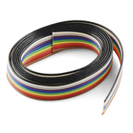
The blue prints show cable clamps on both sides - instead crimp connectors have been used here.   An example of a cable clamp is pictured above right.

Trying to adjust cable length or tension will certainly be problematic with this current arraignment.

These crimped connections shown are as designed:

Large hand sheave pulley

Crimped eyelet supporting Fore Arm

The cable clamps are 6 x 6mm and contain an M3 grub screw to lock the string in place.

Whilst we continue to get the house back in order, I will give consideration what I'll be doing about these missing clamps.

I expect the project will resume in a couple of weeks - and as one dodgy actor once said... "I'll be back!"

Thursday 25 July 2013

Living on Edge

Monday evening we celebrated the new royal baby; we certainly did wet its head, we nearly drowned the poor bugger!!

Once my head cleared next morning, started giving some thought to the interfacing hardware...


As most modern PCB interconnects have very low pitch densities, trying to find something suitable from this era of computing, certainly proved challenging...  I started looking for anything with a contact spacing of 2.54mm (0.1in).

I found the ideal - single sided 10-way female edge connector at RS Components...  Unfortunately, wasn't in stock, Bugger!  Out of desperation placed a back order even though delivery is not expected for another month.

Was just about to close my web browser (Chrome, incidentally) when I spotted these double sided connectors at Rapid Electronics, and ordered one for next day delivery:


And the test fitting...


...certainly was a snug fit !

I can simply ignore, or cut the pins away from the side which isn't needed.  At least the connector itself fits neatly into the recess of the base.

Not sure what the two holes on the right-hand side are...   Answers on a postcard please


Cabling

Ribbon cabling, should be simple to purchase, unless you want 30meters of the stuff !

My travels lead me to SparkFun Electronics and this is why...


3ft of 10-way ribbon, sweet !

https://www.sparkfun.com/products/10649


Checked out the related products, and discovered this...


https://www.sparkfun.com/products/10965

A crimp connector for ribbon cable that is Breadboard Friendly!!

I had not previously given any consideration to this end of the cable...

My idea is... use this connector on a prototyping board, and jumper out to the controlling computer or interface circuitry from there -  it wont really matter if that's a Raspberry Pi, Blackberry, or Blueberry Pies [cliche, sorry]  Cool, eh ?

So, order has been placed; should turn up in a couple weeks from the USA.

Monday 22 July 2013

RISC OS Taster!

I decided not to do my house hold jobs tonight, and started to image RISC OS onto an SD card... hooked up the Pi to my DELL XPS One 27, powered up, and within seconds the entire system had booted...


....I had forgotten how Acorn made use of the middle mouse button - still getting used to it!  Just missing Repton now !

Have to say though, I'm really impressed with the speed of this machine, so quite, and small...


I configured TCP/IP networking support, opened up the web browser to suddenly see... BREAKING NEWS...


Kate had given birth to a baby boy at St. Mary's Hospital, London.  Congratulations are in order, and It's great to hear mother and son are doing well... I'm sure plenty will be celebrating tonight!

I decided to have another Beer on that note... (Not that I need many excuses!)

Anyway, the point of this little exercise was to test the Raspberry Pi and check everything is working correctly.

If anybody out there is afraid of Linux, then RISC OS is certainly a very friendly alternative, and a good way of getting started.  Full instructions how to image operating systems can be found in the Quick Start guide.

I will be imaging Debian onto a separate card which will be used for serious projects going forward, but I'm not going to do that until the Armdroid is sorted...

Pi's up!

This morning, my eagerly waited for Raspberry Pi arrived...


For those who don't already have one, this really is a Credit Card size single-board computer!  The large chip in the middle is the Broadcom BCM2835.  This chip contains the ARM11 core CPU, memory, video display processor, system control, and more.  Everything else you see around the board is concerned with connectivity (video output, audio, Ethernet, USB, expansion ports) and power.

The pins you can see sticking up (top-left) is the General Purpose Input-Output (GPIO) port, and this is what I'll be using to interface the Armdroid.  The pins can be configured to be used for input, or output control.  The neat thing about the Pi is that it also supports a UART, I2C and SPI buses, all giving plenty of flexibility to drive the robotic arm, and leaving scope for some more interesting projects later...

I'm not really going to have a chance to try this until tomorrow evening at the earliest, but I'm definitely going to give RISC OS a quick spin!  This will certainly be like stepping down memory lane to the days of the Acorn Archimedes home computers   :-)

Sunday 21 July 2013

The Base

Removing the base would probably have been easier on models without sensors, but with a little persuasion, the board eventually came out:


The circuit board consists of two main parts - motor drivers and computer interface circuitry.


Driver board

A quick blast of the air duster removed 30 years of dust from the board...  Must actually remember next time not to do that inside the house !


The large edge connection shown in the picture above is where the hand controller connects.  This is not the same interface where the computer would be connected.

A couple of heat sinks were loose, so I pulled these off, and will remount them later with suitable thermal adhesive.


Interface board

On the surface, nothing really alarming to be seen here...


However, on the reverse side, one of the tracks for the edge connector appears to have been purposely cut!

A good 3 - 4mm of track has been scrapped away which can be clearly seen here:


At this stage, I really don't know which track has been cut!   And can't imagine why!

I know the 10 way interface comprises eight data lines (D1 - D8) and power (+5 volts and ground).  The data lines represent data (4-bits), motor select (3-bits), and finally a sync bit.  The sync bit indicates the direction of data travel, to the motors when low, from the micro switches when high.  The transition of state from high to low causes the step pattern to be latched, and allows for more complex, and parallel operations to be performed.

If this track is power, it's not so critical, but it's still an inconvenience, especially for interfacing to a Raspberry Pi (more on this later).  Of course, if this is one of the data lines, then I'll have no option but to repair or replace the circuit board.

As for the interface connection - this is where my documentation gets a bit sketchy.  It would appear Colne Robotics must have revised their circuit boards design at some point.  The documentation describes this interface as a 10way IDC, and certainly I've seen many examples pictured on the internet, but mine uses an Edge-style connector.  The circuit diagrams also bare no resemblance to reality, so reverse engineering, and some common sense will have to make do.


Final thoughts for the day :  I'm somewhat concerned about this interface board, the hand controller connects directly to the driver board which means none of this circuit board has been tested by myself.  I actually have no idea if the electronics work or not!  I'm going to put the base back together for now, and continue sorting out mechanical problems first.  The track can in theory be repaired, luckily this is 1980's technology after all - not your modern multi-layer boards with microscopic SMD componentry, making servicing virtually impossible!


Saturday 20 July 2013

Disarming...

I started stripping the arm down this morning...  After reading the construction instructions a couple of times and plucking up some courage, I eventually unfastened the two bolts holding the arm onto the shoulder...


...and the forearm & upper arm assembly came out surprisingly easy


The shoulder assembly itself was really dirty and greasy, so I started to swab where possible...


...but soon discovered cleaning wasn't going to be possible unless the shoulder side plates are removed... so having decided this, next job was figuring out how to release the reed switches and spacers without loosing everything in the process:


Removing the sensors wasn't such a problem, removing the main drive gearing however was a major hassle... One of the bolts had rusted slightly causing the axle to seize.  It took a number of attempts, and a lot of shouting, and swearing to work things free!

With the sensors, timing belts and drive gearing out of the way, the side plates came out without any further problems:


I also removed all the remaining pulleys from the steppers, the hand motor and it's supporting bracket:


Ah!  Much better now...  Nice and clean!


But... and this is a real big BUT

When I was looking at the main drive gearing I noticed the large pulleys are split, and it wont take much before these guys start failing apart:


You can see the hair line crack in the pulley in the picture above ^^^

What's really worrying, is that all of the reduction gears have failed in this way:


This looks to be real week point in the design.  I'm pretty convinced the base gearing will also be suffering with the same issue.

The sprockets appear standard stock, as too with the 72 teeth single flange pulleys, but they've been pressed together with a little machining.  If anybody out there used to work for Colne Robotics, and can let me know exactly how these parts were fabricated, that would be fantastic... Otherwise, I'm going to have to measure everything up, and call Davall Gears once again!

Next job will involve taking a look inside the base...

Tuesday 16 July 2013

Raspberry Pi

Today, I ordered my Raspberry Pi MODEL B directly from RS Components.  It should arrive here in a couple of days...

I also added the Raspberry Pi Camera Module to the shopping cart, along with a micro-USB Power supply, SD cards, and HDMI cable.   I already have a suitable keyboard and mouse, but decided not to bother with the case.

I ordered blank SD cards as I will do all the operating system imaging myself.  One card is intended for running Raspbian "wheezy" - this is an optimized version of Debian, and I'll be using this for my interfacing projects.   I also bought a card for RISC OS, this is a very neat little operating system, and fancy having a play with it sometime...

I'm not sure what I'll be doing with the Raspberry Pi Camera Module just yet, but it only made sense to order one anyway...

Monday 15 July 2013

A nice day out...

The weather is so nice here in the United Kingdom at the moment, and as it's my birthday weekend, we decided to take the day off, and go for a drive...  I thought I would surprise my wife by taking her here...


This is Davall Gears (http://www.davall.co.uk/) in Hatfield, Hertfordshire which stocks standard off-the-shelf components and manufactures gear wheels and pulleys - I was hoping these guys would be best placed to help with sorting out replacements for the broken pulleys.   And yes, I really am a true romantic!

After arriving at the reception, we was introduced to Ian.  It must have been a funny sight... This couple turning up with a broken Armdroid in a cardboard box.   Anyway, we had a chat and suggested that we might want come back later after giving him the chance to search the warehouse for suitable parts.   Little did I know how complicated Pulleys and Timing Belts can be!

We decided to head to a local pub in Brookmans Park and have lunch.  Returning two hours later, Ian had sorted out all the parts needed, a few pulleys will need ordering from the USA - this is going to take a couple of weeks.

I think while we wait for these bits to arrive, I'm going to start stripping down the arm, look at what other problems I'm going to be facing.  I'll also start cleaning everything as this arm is covered in roughly 30 years worth of dirt and grease.  I'll do another update later in the week to let you know what's happening.

Tooling Up


I have a pretty comprehensive toolkit, but this project is going to require some pretty small spanners as most of the nuts & bots are M3 and M4 sizes.  After reading the user manual suggested tool listing, I decided I'd better tool up...


The rolson micro combination spanner set seemed perfect here, the spanners are arranged with the open and ring-ends for different sizes, this means I only need this one set to undo nuts and bolts of the same size.

I also bought Lock Thread, Silicone Adhesive, a very fine pair of Tweezers, and Digital Caliper.  The digital caliper is something I've always wanted, and I had a great excuse here to buy one!  This will be just perfect for measuring various parts, such as diameter of stepper motor shafts, pulleys, etc.

The lubricants needed for the bearings will be purchased later.  Otherwise, as far as tools are concerned, I'm all set to go...

Sunday 14 July 2013

The one-armed bandit

During 1983 and 1984 my father and I collected the Home Computer Course partwork magazine published by Orbis in the United Kingdom.  At that time, I was 12 years old, and spent my time writing programs on a Sinclair ZX81 and BBC Micro (model-A).  I also tinkered with wires, light bulbs, and speakers, building the most basic of circuits, but my knowledge of electronics was rather limited back in the day.

I was fascinated with robotics, and this is the article which started it...

The Home Computer Course magazine

The article featured the Armdroid 1 robotic arm produced by Colne Robitics Ltd. This was available in kit form, or ready built, and designed to meet the needs of light industrial and educational users.   I wanted one !

Wind forward a few years, I'm studying at University and too my surprise, the computing department was having this clearing out sale (mostly junk).  On the top of the pile was this broken and sorry-full looking Armdroid, and I grabbed it for a mere £20.

The arm was really in a mess, the strings only just holding together, the pulleys on the Steppers broken - the arm simply couldn't support it's own weight!  Next problem... How the hell do I connect it up to a computer?   This was still in the days of pre-Internet... I had the University look in every cupboard and everywhere including the library for any documentation, nothing was found, the arm was soon to be abandoned once again.  Of course, a quick google search today, blue prints, user manuals, and documentation can easily be found.

I recently had the idea of restoring my Armdroid, after all, I've been threatening to do this for a long time.

There are mechanical problems to be sorted, possibly problems with the on-board electronics which is really an unknown quantity, and finally interfacing to a Raspberry Pi.  I have in mind building a web-based application and control the whole lot from an Android based mobile phone, or tablet.

My Armdroid in it's current condition:

Armdroid before restoration

The broken pulleys:

Armdroid - Broken pulleys

I also have the hand controller, and used this to spin up the motors on a bench test many years ago.  All the stepper motors ran well, lets hope they still do...

Armdroid Hand Controller


This blog, which incidentally is my first, will follow this adventure, I'll update as often as possible, but I cannot promise it will be every day.  I hope you'll enjoy reading... and if you have one of these arms yourself, can help, answer my questions, or maybe I can answer your questions, then by all means drop me a message...