Showing posts with label Armdroid 1. Show all posts

Wednesday, 19 August 2015

I2C Port Expander

For all of my projects I have used the standard digital output pins when connecting to the Armdroid's 8-bit parallel interface.  But, what if you want to free up some of these pins in order to use external sensors, controls, or other devices...

The easiest way of getting more inputs and outputs is to use an "i/o port expander".  This is a device that allows you to control a number of ports using data sent to the device.  A port expander takes the data and controls the appropriate I/O pins.  This allows lots of sensors and devices, including the ability to control multiple Armdroids using only a few pins on the Arduino board.

The device I chose was the PCF8574A which has eight general purpose input/output pins controlled using I2C (pronounced I-squared-C).  I2C is a serial communications protocol allowing ICs to swap data on the same two-wire bus - Serial Data Line (SDA) and Serial Clock Line (SCL).

There are other devices available supporting 16 ports (eg. MCP23017), or SPI buses (eg. MCP23S17) and are similar in usage.  Although SPI (10Mhz) is faster than I2C (1.7MHz), for our purpose interfacing the Armdroid, it doesn't really make much difference

Pinouts

PCF8574A pinouts
The expanded I/O port are Pins 4-7 and 9-12 to be connected to the Armdroid interface D1-D8

Three address pins A0, A1, A3 determine the chips ID and must be wired to either +5v or GND.

Pin 13 (INT) used for interrupt output - leave disconnected for now

SDA - SDA pin on Arduino
SCL - SCL pin on Arduino
Vcc - +5v on Arduino
GND - GND on Arduino plus Armdroid interface GND

The 8574A can be assigned an address in the range 0x38-0x3F, and you can change this address by changing the connections of the pins A0, A1, and A2 as shown in the following table:

A0
A1
A2
Address
GND GND GND 0x38
+5V GND GND 0x39
GND +5V GND 0x3A
+5V +5V GND 0x3B
GND GND +5V 0x3C
+5V GND +5V 0x3D
+5V +5V GND 0x3E
+5V +5V +5V 0x3F

You can use up to eight of these PCF8574A chips on the same IC2 bus.  Texas Instruments also manufacture the PCF8574 (without the A), essentially the same device with addresses ranging from 0x20-0x27.

You might find this i2c_scanner_sketch useful to verify your I2C communication is working if you have any problems.

Circuit Diagram


Circuit diagram for 8-bit Armdroid interface with PCF8574A

PCF8574A / Armdroid 1 connections:

P0 (pin 4) - D2 (J1/pin 4)
P1 (pin 5) - D1 (J1/pin 3)
P2 (pin 6) - D4 (J1/pin 6)
P3 (pin 7) - D3 (J1/pin 5)
P4 (pin 9) - D6 (J1/pin 8)
P5 (pin 10) - D5 (J1/pin 7)
P6 (pin 11) - D8 (J1/pin 10)
P7 (pin 12) - D7 (J1/pin 9)

J1/pin 1 (+5v) - not connected
J1/pin 2 (Gnd) - Common Gnd (Arduino & PCF8574A)

The address of the PCF8574A is hard-coded to 0x38 by grounding A0, A1, and A2.  I would recommend starting with these settings until you have something working.

Code

Surprisingly, the code changes to support the port expander in the Armdroid Library are minimal thanks to C++ inheritance, and the Arduino 'Wire' library.

When designing the Armdroid library, flexibility was foremost, and it was always my intention to allow the library to be easily adapted for use in different projects.

To make this possible, core functionality was implemented in an abstract base class which can be derived into specialized classes.  This base class doesn't actually have any knowledge how control the hardware, rather, its up to the derived classes to implement that.  Another potential use in future might include supporting optimized versions for different Arduino boards.

In our case, we're creating a new class ArmdroidPortExp inheriting from ArmBase to represent our port expander variant:

 class ArmdroidPortExp : public ArmBase {  
  public:  
  void begin(uint8_t address = 0x38);  
  protected:  
  void armdroid_write(uint8_t output);  
  private:  
  uint8_t i2c_addr;  
 };  

This implementation adds a new member function ArmdroidPortExp::begin(uint8_t address) responsible for setting up the I2C hardware, and stores the supplied address of the port expander.  We also take the opportunity to initialize the Armdroid interface at this point.

The virtual function ArmdroidPortEx::armdroid_write(uint8_t output) simply writes a byte to the port expander using the address supplied earlier.  This is all done using the 'Wire' library that conveniently abstracts us from low-level I2C protocol/transmission details:

 void ArmdroidPortExp::begin(uint8_t address)  
 {  
  i2c_addr = address;  
  Wire.begin();  
  Wire.beginTransmission(i2c_addr);  
  Wire.write(STROBE);  
  Wire.endTransmission();  
 }  
 void ArmdroidPortExp::armdroid_write(uint8_t output)  
 {  
  Wire.beginTransmission(i2c_addr);  
  Wire.write(output);  
  Wire.endTransmission();  
 }  

The implementation really is that simple !

Finally, here's a snippet of code that instantiates and uses the newly derived class...

 #include <Wire.h>  
 #include "Armdroid.h"  
 #include "ArmdroidPortExp.h"  
 // port expander address:  
 const int i2c_addr = 0x38;  
 // initialize Armdroid library:  
 ArmdroidPortExp myArm;  
 void setup()  
 {   
  myArm.begin(i2c_addr);  
  myArm.setSpeed(120);  
  myArm.torqueMotors(true);  
 }  
 void loop()  
 {  
      .  
      .  
      .  
 }  

I've added this code as an extension to the Armdroid Library as a separate package:
https://github.com/Armdroid/Armdroid-Arduino-PortExp

It wasn't possible to add this code to the library without introducing a dependency on the Wire library due to an 'oddity' with the Arduino IDE build mechanism.  If you intend to make use of these extensions, you will need to first install the Armdroid-Arduino-Library, then follow the instructions to install Armdroid-Arduino-PortExp

Included with this library is a modified version of the AsyncDemo previously presented with the Asynchronous library enhancements.

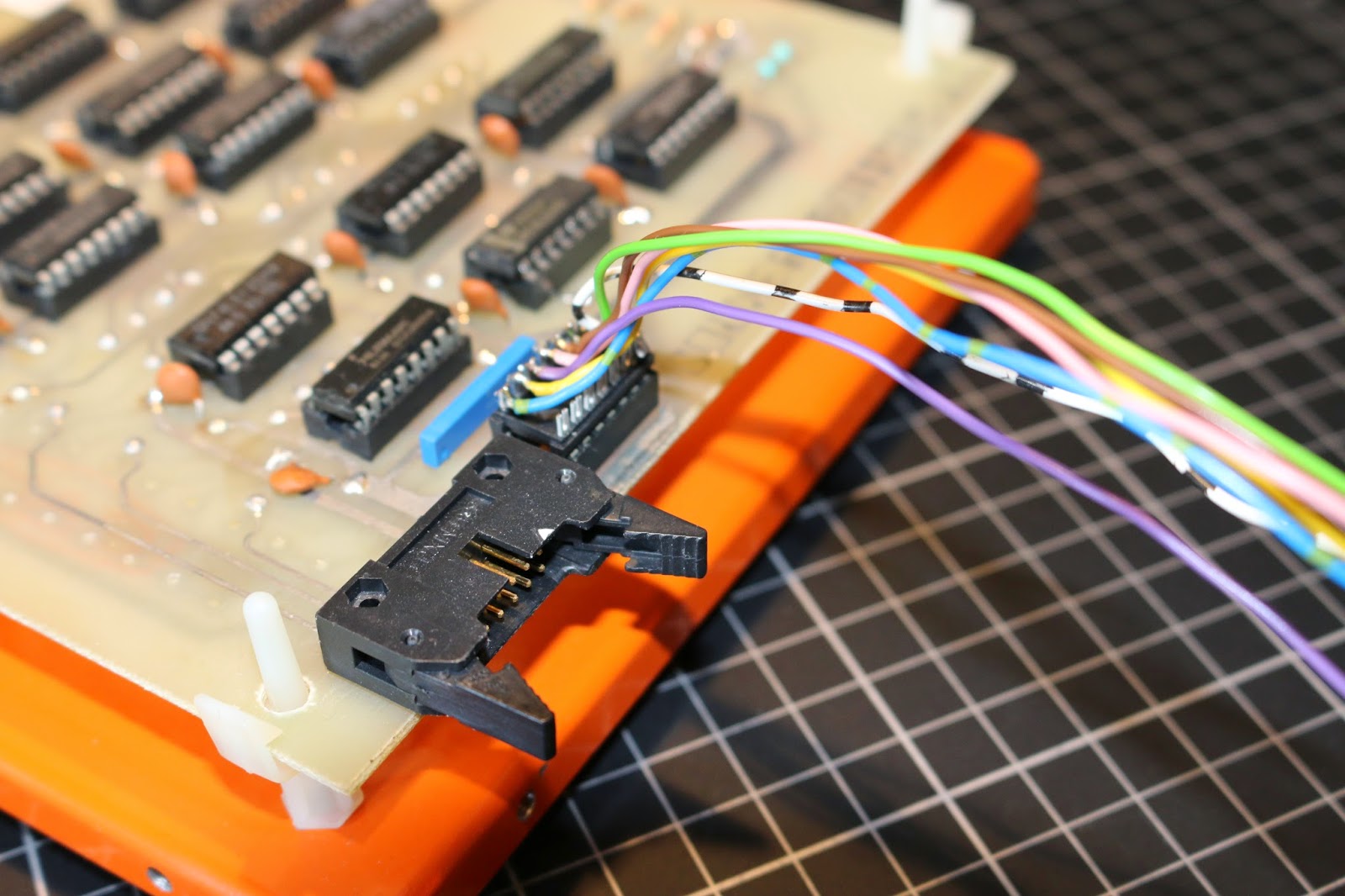
Photographs of my test circuit for reference:

See Also

PCF8574A data sheet: http://www.ti.com/lit/ds/symlink/pcf8574a.pdf
I2C tutorial: http://www.robot-electronics.co.uk/i2c-tutorial
Arduino wire library: https://www.arduino.cc/en/Reference/Wire

Standard Armdroid / Arduino wiring:
http://armdroid1.blogspot.co.uk/2014/02/interface-bench-test-part-1.html
http://armdroid1.blogspot.co.uk/2014/02/interface-bench-test-part-2_15.html
http://armdroid1.blogspot.co.uk/2014/02/interface-bench-test-part-3.html

Monday, 13 July 2015

Wi-Fi-controlled Armdroid

Back during Easter Bytes at TNMOC, a visitor to the museum asked if it's possible to control the Armdroid on display using their Mobile Phone or Tablet Device...   This got me thinking, and decided to hack something together for the following weekend...

If your interested in controlling your Armdroid using Wi-Fi or across the internet, here's how you can setup your own stand-alone, web-enabled Armdroid, using the Arduino Yun.   When you're done, you'll be able to control your Armdroid using any web-browser, or control programmatically over the internet using Python or other scripting languages.

What exactly is the Arduino Yun you might be asking.... It's basically a combination of a classic Arduino Leonardo (based on the ATmega32U4 microcontroller) with a WiFi system-on-a-chip Atheros AR9331 running Linino (a MIPS GNU/Linux distribution based on OpenWrt).  The two processing units are connected together using the Bridge library allowing you to combine the power of Linux with ease of Arduino.

OpenWrt supports REST services for clients and servers.  REST is an acronym for "Representational State Transfer".  It is a software architecture that exposes functionality through URLs.  REST has gained widespread acceptance across the World Wide Web as a simple alternative to SOAP and WSDL-based web services.   A nice introduction to the concepts behind REST can be found here.

This project implements an Armdroid REST API allowing functions of the robotic arm to be manipulated through URLs.  I've prepared a simple web page that consumes this service to get you going, although you could easily interact with this from say, a Raspberry PI using the CURL library, etc.


The photographs above shows the project from Easter Bytes.  In this arrangement, we configured the Yun's WiFi as a standalone Access Point - visitors would simply connect to this network using a Mobile Phone web-browser, then take control.   This actually proved to be a real hit with many visitors to the museum, and was especially rewarding to get usability feedback from a 7-year old! (pictured)

You can see the simplicity of the set-up in the following photographs:

I've added the source code for this project to the Armdroid Library examples directory  https://github.com/Armdroid/Armdroid-Arduino-Library

If you wish to use the sample web page, you'll need to prepare a memory card by creating the directory structure "arduino/www" which ensures the Yun will create a link to the SD card "/mnt/sd" path.

The REST API is structured around verbs and Armdroid functions - for example, you want to move the shoulder stepper motor x steps, you would simply issue an HTTP web request like http://arduino/armdroid/shoulder/position/x.   Likewise, other Armdroid functions are described by their function - base, elbow, gripper etc.

If you wish to determine what is the current location for any stepper motor, you would use a URL such as http://arduino/armdroid/shoulder/position (without position value) and this will return in the response the offset counter for this channel.

The complete REST API comprises of the following URL structure:
  • http://myArduinoYun.local/arduino/armdroid/base/position : returns base motor offset counter
  • http://myArduinoYun.local/arduino/armdroid/base/position/x : rotates base motor x steps clockwise or counterclockwise
  • http://myArduinoYun.local/arduino/armdroid/base/position/x/y : rotates base motor x steps clockwise or counterclockwise at y revolutions-per-second
  • http://myArduinoYun.local/arduino/armdroid/base/sensor : returns base sensor reading
  • http://myArduinoYun.local/arduino/armdroid/shoulder/position : returns shoulder motor offset counter
  • http://myArduinoYun.local/arduino/armdroid/shoulder/position/x : rotates shoulder motor x steps clockwise or counterclockwise
  • http://myArduinoYun.local/arduino/armdroid/shoulder/position/x/y : rotates shoulder motor x steps clockwise or counterclockwise at y revolutions-per-second
  • http://myArduinoYun.local/arduino/armdroid/shoulder/sensor : returns shoulder sensor reading
  • http://myArduinoYun.local/arduino/armdroid/elbow/position : returns elbow motor offset counter
  • http://myArduinoYun.local/arduino/armdroid/elbow/position/x : rotates elbow motor x steps clockwise or counterclockwise
  • http://myArduinoYun.local/arduino/armdroid/elbow/position/x/y : rotates elbow motor x steps clockwise or counterclockwise at y revolutions-per-second
  • http://myArduinoYun.local/arduino/armdroid/elbow/sensor : returns elbow sensor reading
  • http://myArduinoYun.local/arduino/armdroid/wrist/pitch: returns both LHS and RHS wrist offset counters
  • http://myArduinoYun.local/arduino/armdroid/wrist/pitch/x : counter-rotates wrist motors to pitch gripper up/down
  • http://myArduinoYun.local/arduino/armdroid/wrist/pitch/x/y : counter-rotates wrist motors to pitch gripper up/down at y revolutions-per-second
  • http://myArduinoYun.local/arduino/armdroid/wrist/rotate : returns both LHS and RHS wrist offset counters
  • http://myArduinoYun.local/arduino/armdroid/wrist/rotate/x : rotates wrist motors to roll gripper clockwise/counterclockwise
  • http://myArduinoYun.local/arduino/armdroid/wrist/rotate/x/y : rotates wrist motors to roll gripper clockwise/counterclockwise at y revolutions-per-second
  • http://myArduinoYun.local/arduino/armdroid/wrist/left/position : returns LHS wrist offset counter
  • http://myArduinoYun.local/arduino/armdroid/wrist/left/position/x : rotates LHS wrist motor x steps clockwise or counterclockwise
  • http://myArduinoYun.local/arduino/armdroid/wrist/left/position/x/y : rotates LHS wrist motor x steps clockwise or counterclockwise at y revolutions-per-second
  • http://myArduinoYun.local/arduino/armdroid/wrist/left/sensor : returns LHS wrist sensor reading
  • http://myArduinoYun.local/arduino/armdroid/wrist/right/position : returns RHS wrist offset counter
  • http://myArduinoYun.local/arduino/armdroid/wrist/right/position/x : rotates RHS wrist motor x steps clockwise or counterclockwise
  • http://myArduinoYun.local/arduino/armdroid/wrist/right/position/x/y : rotates RHS wrist motor x steps clockwise or counterclockwise at y revolutions-per-second
  • http://myArduinoYun.local/arduino/armdroid/wrist/right/sensor : returns RHS wrist sensor reading
  • http://myArduinoYun.local/arduino/armdroid/gripper/position : return gripper motor offset counter
  • http://myArduinoYun.local/arduino/armdroid/gripper/position/x : rotates gripper motor to open/close fingers
  • http://myArduinoYun.local/arduino/armdroid/gripper/position/x/y : rotates gripper motor to open/close fingers at y revolutions-per-second
  • http://myArduinoYun.local/arduino/armdroid/gripper/sensor : returns gripper motor offset counter
  • http://myArduinoYun.local/arduino/armdroid/torque/enabled : returns a value indicating torque has been applied to all motors
  • http://myArduinoYun.local/arduino/armdroid/torque/enabled/x : enables/disables torque
  • http://myArduinoYun.local/arduino/armdroid/home : returns to home (starting) position
All responses are returned using JSON (JavaScript Object Notation) formatted replies allowing simplified parsing in many programming languages.

If your interested to understand how the code works - you need to first understand how the Bridge example works as a starting point - see https://www.arduino.cc/en/Tutorial/Bridge

Basically, each of the six channels (base/shoulder/elbow/left wrist/right wrist/gripper) are implemented using a command method as follows:

 void baseCommand(YunClient client)  
 {  
  String baseCmd = client.readStringUntil('/');  
  if (baseCmd.startsWith("position")) {  
   // read number of steps, if none have been specified, parseInt()  
   // will simply return zero which will be ignored, and we'll  
   // finish by feeding back current position to the client.  
   const int steps = client.parseInt();  
   if (steps != 0) {  
    // if the URL includes a speed value, use it  
    int whatSpeed = DEF_MOTOR_SPEED;  
    if (client.read() == '/') {  
     const int speedInRpm = client.parseInt();  
     if (speedInRpm > 0)  
      whatSpeed = speedInRpm;  
    }  
    // drive motor to rotate base clockwise/counterclockwise  
    driveMotor( ARMDROID_BASE_CHANNEL, steps, whatSpeed );  
   }  
   // send feedback to client  
   client.print(F("{\"base-position\":"));  
   client.print(getPositionReading( ARMDROID_BASE_CHANNEL ));  
   client.println(F("}"));  
  }  
  else if (baseCmd.startsWith("sensor")) {  
   client.print(F("{\"base-sensor\":"));  
   client.print(getSensorReading( ARMDROID_BASE_CHANNEL ));  
   client.println(F("}"));  
  }  
  else  
   client.println(F("ERROR: invalid base command"));  
 }  

The code begins by reading the client URL and tries to match the "position" command.  If this is present, we can then determine if the URL is specifying a value representing the position in which to drive the motors, or alternatively, we'll simply report on the current position.  If we do have a valid "position" command then we look to see if a speed has been specified.  If this is not the case, the default (120 RPM) will be used instead.

If the command matches "sensor" then we have the ability to return the current sensor reading for the given channel.

In either case, after calling the Armdroid Library to perform the desired function, we send feedback to the client such as the new position after the operation completes.


Limitations

Yun's web server times-out after approximately 5seconds when performing lengthy Armdroid operations.  This is mostly due to the design of the current Armdroid Library which is synchronous in operation, or blocking, when running motors for long periods of time.  In this situation, a response doesn't get returned from the microcontroller before the web server gives up, and returns 500 (Internal Server Error) back to the client.

This isn't immediately obvious using the example web page, although can be easily demonstrated when browser debugging is enabled:
Fig 1. short base rotation (200 steps)
Issuing the request /arduino/armdroid/base/position/200 rotates the base stepper motor 200 steps resulting in HTTP status code 200 (OK) returned.  You can see the reply includes our JSON response indicating the position (current offset counter) of this motor channel after performing the operation.

Now observe what happens when the request is made with 2000 steps:
Fig 2. lengthy base rotation (2,000 steps)
HTTP status code 500 is returned after 5seconds, and before the motor has finished running.  By the time the motor reaches the target position, the connection no longer exists, no response is returned.


We'll revisit this when Asynchronous enhancements have been added to the library, but in the meantime, you can work around this by calling the API to retrieve the current position and wait if necessary until the previous operation has completed.

The sample web page included with the example is very basic...  It serves purely as a demonstration only... if you want something with more sex appeal, you might want to look at DoJo or similar frameworks to create a richer experience.

Tuesday, 13 January 2015

Infrared Remote Control

I realise it's been a long time since writing anything here...

Today, I'm going to share with you my Armdroid Remote Controller project, which was quickly hacked together for demonstrating the Armdroid 1 during a recent meeting of volunteers at TNMOC.

The circuit makes use of a single TSOP4838 IR receiver module along with some rather cleaver programming that decodes key presses and operates various Armdroid functions.

I'll be including the source code for this project as an example sketch in the forthcoming release of Armdroid Library on GitHub.

The project works surprisingly well, although movements to preset positions are made point-2-point (P2P), which is slightly different to continuous path movements.  This is after all, a demonstration, although could be easily extended to support waypoints and recording/playback of movements.

I've been using an old Sky remote control handset, you'll need to change the scan codes to match your hardware, although instructions will be included how to do this.

Connecting an infrared receiver module is relatively simple, the sensor output is connected to a spare digital input on the microcontroller.

ArmdroidShield (version 1) utilizes pins 2-9 for connecting to the Armdroid's 8-bit parallel interface, so pin 10 was chosen for this purpose, along with +5V and Gnd connections.  There are many common IR receiver modules available.  Check the datasheet for your device to ensure that you connect it correctly.

The software works by decoding the IR signals to digital pulses that correspond to buttons on the remote.  A scan code lookup table is then used to assign Armdroid functions to key presses.   This table uses function pointers to simplify the program logic, also included are methods for Rolling/Pitching the Gripper, along with routines for calculating target offsets when moving to new positions.


Saturday, 15 November 2014

Arduino ArmdroidShield

The restoration of TNMOC's Armdroid is getting closer to completion, and attention has shifted towards designing suitable displays for the robot at the museum.

Initial displays are likely to be Arduino based, and in time, we'll probably add other historical computers into the mix.   In the meantime, something I had not given much thought about, was what to do with my 'temporary' breadboard interface that's been used over the past year, a more permanent solution is however needed.

So, a couple of weeks ago, I decided to design a PCB to be called.... wait for it.... ArmdroidShield !

Having a purpose made PCB will of course be more reliable, and better suited to a harsher museum environment.  The goal was to keep things flexible - perhaps we'll use these at a future Summer/Winter Bytes and students can design other Armdroid-based control systems, so making the board using a Shield design, was an obvious choice.

This was my first attempt at designing a double-sided PCB.  Fortunately, the design doesn't require many components, so from start to finish - 2hrs including inspection of final design, and correcting contacts positioned too close together.

The PCB arrived the following week directly from the fabricator, and as you can see the results are pretty good:

ARDUINO ArmdroidShield

The shield has been designed around the Arduino R3 header standard making it compatible with the following products:
  • Arduino Uno (Revision 3)
  • Arduino Leonardo
  • Arduino Yun
  • Arduino Ethernet
  • Arduino Tre & Arduino Zero (when available)
It's a very simple board, really just an adapter - only Digital Pins 2 through to 9 are utilized, along with common grounds.

The tricky bit was soldering the Stackable Headers and keeping everything properly aligned, but with perseverance, got there in the end.

ARDUINO ArmdroidShield

ArmdroidShield installed on the Arduino Leonardo:


Completed assembly ready for bench testing:


Monday, 6 October 2014

TNMOC Armdroid 1

The restoration work is progressing well, a few issues remain with the gripper and timing belts.  Hopefully, we'll have this heading to the museum in a few weeks :
Pictured TNMOC's Armdroid 1 and power supply

Tuesday, 16 September 2014

Sensors

Finally, the original proximity sensors have been refitted to my Armdroid, and a new wiring harness completes the installation work.  As you may recall, they had been removed earlier when diagnosing tight-spots in the mechanics.


Machining new aluminum spaces was probably the most time consuming part.  The original spaces were in bad shape and had a tendency to rub on the reduction pulleys with the timing belts, this caused friction and as result, performance suffered.


The sensors are aligned perfectly to reduction gearing.  Setting up can be tricky - a multimeter comes in handy for testing, and making position adjustments.

All sensors have been positioned within a millimeter of reduction gearing, and more importantly, no longer make any physical contact.

The new 6-core wiring harness, connecting the four sensors mounted on the rear support bar, front-mounted gripper sensor, and Base position sensor was installed:


The hand sensor is still a mystery, see previous post Magnet Madness
For now, accepting the fact this won't do anything useful, have purposefully left disconnected and will decided later what I'm doing here.

Update:  Its a shame Colne Robotics didn't invest in designing a decent gripper tension feedback mechanism similar to that employed in the Microbot MiniMover-5 triggering a micro-switch contact under tension, or the gripper is completely closed.
Pictured to right - TNMOC/Armdroid showing sensor installed under Right-Hand Wrist function.  Not convinced this is correct either, sure, it will work, but leaves the Left-Hand Wrist monitored by only one sensor.

Another grey area in the instructions is chassis grounding - prototype models had their 7805 voltage regulator bolted to the chassis which grounds the circuit to the metal work.  Later, single-interface models do not do this, so a chassis ground cable was included in my wiring.   This will allow me to easily switch between interface circuits.


Tracing the circuit, the majority of the 14-pin header for the feedback sensors are ground connections.
Also, note, in Input Mode, the port address line D2 (header pin 8) is spare - no connection


This configuration is likely to change, but these are my current assignments:

Microswitch Assignment to Functions INPUT BIT CABLE / PIN
Forearm MS1 (D3) Yellow (13)
Left Wrist MS2 (D4) Brown (12)
Right Wrist MS3 (D5) Green (9)
Shoulder MS4 (D6) Pink (11)
Gripper MS5 (D7) Purple (9)
Base MS6 (D8) Blue-Green (14)


Monday, 25 August 2014

Bearings & Shoulder Rebuild

A rainy Bank Holiday in the UK, so what a better way to spend the day..... playing with Armdroids of course !!

Its been a while since touching my Armdroid, or the one being restored for The National Museum of Computing, and decided today, I would strip down the base, clean, and inspect every individual part before rebuilding again.

I've not previously covered anything on the Blog about the Bearing Assemblies, so thought this would be well worth some coverage here.

The following picture is a recap from last year, what my bearing assembly looks like:


This is a custom machined from Aluminum which forms the following components: (1) Base Bearing support column, (2) Shoulder Bearing support, and (3) Bearing adjusting ring (pictured with grub screw).  This is complimented by 24 ball bearings fitted around the upper and lower flanges.   Reading the construction notes, I imagine its quite a fiddle to assemble, keeping the ball bearings in place whilst turning over to work on the opposite side.

When first inspecting TNMOC's Armdroid, I always knew there was a difference with the bearings, but couldn't see clearly what was happening under all the dirt 'n grime, but, check this out - beautifully machined from solid brass


...which accepts flat needle-type roller bearings with steel shims for the upper and lower supports:


This is how the top of the assembly looks without the other assembles installed:


I'm guessing a previous owner made this as a repair, or perhaps an enhancement to the original assembly
Update:  After searching the internet and examining further photographs, I've now seen plenty of other examples of this arrangement, implying Colne Robotics introduced this as a later improvement.

The center bore for the cables is a lot narrower than the original assembly which does make feeding of cables tricky.  Another observation with this design - its no longer possible for users to make adjustments here.

The original assemblies can be easily damaged by cross-threading the adjustment ring, so be careful not to over-tighten if you need to make any adjustments here.

Having stripped all this down, gave it a jolly good clean, lubricated all moving parts, rotates like a dream now!

I've added more photographs of the rebuild below - might be useful if your rebuilding your base and shoulder and need a reference.

Saturday, 2 August 2014

Talk about Torque

The Armdroid Library on GitHub has just been updated with an enhancement allowing Holding Torque to be released or re-applied, and this is especially useful when recovering the robot after things have gone badly wrong, or runaway.

Holding Torque is defined as the amount of stationary torque required for a stepper motor to remain in a fixed position.

This is unlike operating torque (max and minimum) which is the torque a stepper motor can apply when experiencing zero resistance.  Changing voltage will of course, change this torque rating.  Additionally, there is stall torque, which is the torque a stepper motor requires when powered but held so it cannot rotate.

The specifications of the ID35 stepper motors used on the Armdroid are rated with a holding torque of 8.5Ncm (newton centimeters) and its almost impossible to manually articulate any joint while these coils are energized.  The enhancement made to the firmware library allows stepper motors to be freed under computer control, making it possible to manually re-position the arm.  The steppers can then be explicitly torqued again to hold the new position, or by simply running the motors again will indirectly do this.

Another potentially useful purpose is power saving when the arm is idle for long periods of time.

 void ArmBase::torqueMotors(boolean torqueEnabled)  
 {  
  for(uint8_t motor = 0; motor < 6; motor++)  
  {  
   MTR_CTRL* const mtr_ctrl = &mtr_control_table[ motor ];  
   // combine with coils off pattern + control bits if disabling holding torque, otherwise  
   // reinstate coil pattern from last step index  
   const uint8_t output = (torqueEnabled ? mtr_waveform_table[ mtr_ctrl->step_index ] : FREEARM) + mtr_ctrl->address + STROBE;  
   // write command to Armdroid port  
   armdroid_write( output );  
   armdroid_write( output - STROBE );  
   delay(1);  
  }  
  // ensure Armdroid is returned to Input mode  
  armdroid_write( STROBE );  
 }  

To accommodate this new method, a slight modification was necessary to the Armdroid Serial Remote Control protocol, but still remains compatible with the existing revision.


Sunday, 13 July 2014

Wrist Designs

Over the past couple of weeks I have been mostly testing Armdroid electronics and going completely round in circles...

I've somehow destroyed an Arduino, questioned my sanity, sacrificed several chickens, and finally, have the interface electronics from TNMOC's Armdroid now running.  But, I'm facing what appears to be a timing problem as soon as the 74LS366 is inserted into the empty IC5 socket that enables the feedback sensors.

I was wondering why TNMOC's interface was missing this chip, because it doesn't make a great deal of sense when the arm has already been fitted with sensors.  When you look back at the photographs it's quite obvious the previous owner bypassed the interface circuit and controlled the steppers and sensors  from some other source.  This is not the first time I've witnessed this when making a post-mortem analysis of a dead looking Armdroid.

Enabling IC5 and testing the same combination with my Armdroid interface circuit, everything is working as expected, so assuming I do have my facts correct, I will write up another day more information about the wiring up of these sensors.

I suspect the timing problem relates to the 74LS123 (IC4) Monostable Multivibrator and delay determined by the accompanying capacitor and resistor network.   Testing this capacitor with my ESR meter in-circuit proved inconclusive, so I'll probably swap this out as soon as I have replacements available and try again.

Anyway, having spent many hours looking at the circuit board, decided I would take a break and start cleaning up the mechanics as everything is really dusty and dirty....   This morning I spotted a very subtle difference between my Armdroid 1 hardware and TNMOC's regarding the finger supports.

On the surface, the design of Armdroid 1 hardware didn't actually change a great deal after going into production, so this is worth a quick mention here...

Spot the Difference

As you can see in the following photograph - my Armdroid consists of an aluminium support flange for the three fingers:

Finger Support Flange - my Armdroid
Ignoring the fact the DELRIN gearing have different colours, this design consists of two different types of bevel gears - flanged gears (the ones with string wrapped around them) and one non-flanged gear, called the hand gear, which this finger assembly is attached with machine screws.

This must have changed at some point to the following arraignment which appears much simpler.  In this case, we have three identical bevel gears with much larger flanges, and the aluminum support is no longer necessary because the fingers are now bolted directly to the gearing:

Simplified finger supports on TNMOC's Armdroid
Another view of the flanged bevel gearing

Looks obvious this must have been a cost cutting exercise, but did Colne Robotics ever update their documentation and blueprints to reflect this ?     Answers on a postcard please...

Sunday, 15 June 2014

Publications

Yesterday was spent digging through the archives, along with pot-holing the darkest depths of D-Block at TNMOC, and my efforts was truly rewarded with some remarkable discoveries...


These are original ETI (Electronics Today International) magazines featuring the Armdroid prototype.

Armdroid Part 1, September 1981 - pages 50 - 57
Armdroid Part 2, October 1982 - pages 43 - 46

There are a number of copies of Part 1 floating around the internet, although most are fairly blurry, so can be difficult making out the circuit & timing diagrams.

I've never seen the October issue before, so this was especially exciting....  Part 2 covers the full component listings, PCB overlays, and Power Supply in more detail.   Interestingly, they must have changed this design because the PSU is described as providing +12v and +5v power outputs, whereas on my Armdroid (prototype), the power connector takes a single +12v input and regulates to +5v using a 7805 bolted to the chassis.  The later single interface models incorporate this regulator on the circuit board itself.

There are no other hardware differences between what's presented in these articles, with the exception of the base unit which appears to have changed from a rectangular steal box.

BYTE reviewed the Armdroid in May, 1982, Vol 7, No. 5 titled "Japanese Computers" - pages 286 - 294


The review is really interesting, the reviewer (Steven Leininger) had the kit to assemble, plus a factory assembled Armdroid for reference.  He had preliminary version of the construction manual, but I suspect this didn't improve for the final version...  A criticism was made about the manual specified part numbers, but didn't refer to drawing numbers - something that's caused me a great deal of headaches.

He had problems assembling the duel-race ball-bearing assembly, something I've never attempted, but this might have been easier with better quality drawings with detailed close ups.

The reviewer interfaced his Armdroid to the TRS-80 Model I - that's not really a surprise because Steven Leininger was actually the design engineer for this microcomputer.  The rest of the article covers the LEARN software and some of editing features for designing movement sequences.

Scanned copies of these articles and can be found in the resource section.  Because of age and quality of paper, the quality of these scans are not perfect.

Other Publications

I'm still researching the archives, the only other magazines which feature articles relating to the Armdroid are:
The Home Computer Course, part-work magazine - pages 314 - 315 (published 1983/4).


If any additional material comes to light trawling through the library & archives, I will update this Blog post.  If anybody else knows of any other published material relating to Armdroids, please let me know.

Friday, 9 May 2014

TNMOC restoration project

Over the past few weeks I've been in discussions with The National Museum of Computing regarding helping out with the restoration of their recently donated Armdroid 1, and guess what....

I've enrolled as a member of the volunteering staff, and will shortly start work on my first restoration project for the museum.   Looking at the overall condition of this, I really can't imagine this will take very long....

Sure, its dusty, a little bit rusty in places, but on the whole, the mechanics look to be in amazingly good condition.

The reduction gears, do however appear to have suffered from those hair-line fractures, which I've previously talked about as a fairly common problem, but, there really is nothing here that cannot be replaced or repaired.

That said, I'll be stripping down the entire mechanics, possibly separating the bearing housing, ensure everything is cleaned and lubricated before rebuilding.

We'll need to re-string with new Kevlar, and as I have spare timing belts, we'll change these too.

Mind you, I have no idea what condition the electronics are in, but the same approach to testing this circuit will be employed as before.

Peeking inside, I could identify an Issue 4 driver board, which is exactly the same revision as my production board, but with all the wires hanging outside.... yeah...well... who knows at this stage !

It's really nice to have an original power supply, I've never seen one before, and I'm looking forward to seeing if this works.  The PAT test (UK electrical safety) sticker is dated 1999, so possibly its been a while since last use.

The intention is to put this on interactive display in the museum - I've always liked exhibits in museums with buttons to press, making things work....  and most likely, this will use a Raspberry Pi or Arduino as the controller behind the scenes.

My new patient close-up :


I intend to draw-up schematics of this power supply as I don't believe these are published anywhere on the internet.  I have seen circuit diagrams for the original prototype power supply, but they do differ in output voltages.

I'm not intending to update the Blog with every step of this rebuild, but if anything interesting is discovered, or different to what has been previously covered, then I'll certainly make an update.

Readers of the Blog will know I'm currently developing an updated version of LEARN for Windows, whilst this activity is still taking place, it is likely to be delayed a little.


Of course, one of the benefits of volunteering your services, is that you get to play with lots of nice kit, and this could possibly be my next "big" project....    Take a look at this beast.....


It's a manipulator arm from a submersible Remotely Operated Vehicle (ROV), previously used in the North Sea from the Oil & Gas Industry.

We believe this was would have been used for Inspection Repair Maintenance (IRM) work at depths of around 50 - 300 meters.

It runs on Hydraulics operated from electromechanical values, with control signals feeding down an umbilical cable from the surface vessel.  The operators controlling the ROV and ARM would be aboard this vessel.

Gripper close up
With a gripping force around 1000 lb (454Kg), this is somewhat stronger than the mere 5 lbs the Armdroid is good for!   I'd say, keep your fingers well away!

Base Arm Cylinder was removed for packaging
In the photograph above you can clearly see the black hydraulic lines with grey sheathing to group them.  The transparent brown sheath caries multiple signal wires, which we believe run from positional encoders, and possibly other solid-state sensors.

The signal cables and hydraulics feed into the value assembly.  There are 14 hydraulic actuator lines in total.

Hydraulic Valves
We believe a hydraulic feed from the ROV supplies these valves - there is no separate hydraulic pump.  You can also make out the pressure monitor inside opposite the hydraulic feed lines on the right.

The large blue cable contains multicore signals and feed into this, which appears to be some kind of transformer / interface unit that would be strapped somewhere to the ROV structure.


The connector on the left is labelled 110v which we believe carries both power and serial data.

Everything about this arm is unbelievably heavy, making it somewhat difficult to inspect everything.  Luckily, Daniel Bull was around to help lift things.

We've started researching the manufacturer, history, and have reason to believe the software may have been developed in Milton Keynes.

Although we're missing a hydraulic pump, we're wondering if it's actually possible to resurrect this thing back to life....   I don't claim to know anything about hydraulics, but we'll be reaching out to experts in the industry.   Crazy... yep, I'm sure we'll have lots of fun in the process !

One of the operator's control panels

Although damaged, the controller reflects each degree of freedom of the manipulator.  There is certainly a possibility we could re-purpose this as an Armdroid controller.

I'm actually wondering....  Has anybody out there interfaced a Raspberry Pi to an ROV manipulator arm, or would that be a first ?

It might be possible to interface the valve assembly directly to the GPIO with appropriate drivers and buffers.  This takes the high-voltage out of the equation, and saves us figuring out that serial protocol....

Of course, if you recognize the above hardware or have experience of ROVs - operating or engineering please do drop me a message.

Google+If you want to find out more, be sure to follow on Goggle+ as that's where all my adventures at TNMOC will be posted - I'm trying to keep this an Armdroid blog after all.   Additional photographs of this project will also be added here.