Tuesday 25 March 2014

Armdroid Library

The software section has been just updated to include the newly released Armdroid Library and includes details of the GIT source repository.

The Armdroid Library has been developed especially with portability in mind, but at the moment, only Arduino is currently supported.  Hopefully this will change when support is added for other platforms and micro-controllers.

Summary of key library features:
  • Responsible for all low-level control & dynamics
  • Configurable which I/O pins are used for interface connections
  • Reusable class structure design
  • Drives single/multiple motors
  • Variable speed control
  • Maintains channel offset counters
  • Custom motor channel re-mapping (table driven)
  • Supports multiple addressing modes

The library includes examples, which also contains the slave Serial Driver uploaded to my Arduino Leonardo and demonstrated at UCP (see previous post) driven by a Raspberry Pi.   More example programs will be added, and I'll also be writing various Tutorials how to write your own programs, and build different interfacing circuits using this library.

The library currently supports different Armdroid models - this includes addressing modes for both "prototype" and "production" models with the single-interface boards.  Prototype variants will however need to be configured as Direct-Drive (see resources section for clarification).  By default, the library assumes your interfacing a production model; otherwise for prototype models, simply add #define INTERFACE_PROTOTYPE  before all include statements in your sketches.

Hopefully, owners wanting to experiment with interfacing their Armdroid to Arduino (and later Raspberry Pi) will be interested in this library, and all comments/suggestions for enhancements gratefully received.

That said...  I've also been receiving correspondence from people interested in controlling their Armdroid from IBM PC and compatibles.  Of course, Arduino is ideal for achieving this purpose, and is relatively inexpensive.  We can use USB/Serial connectivity to interface the device, and the same Serial Driver program included with the library can be used without modification.

Because of the amount of interest shown, a slight digression will include developing a variant of LEARN for Windows.  This will be followed with Tutorials how to install, and configure the software.

Sunday 23 March 2014

Jammin' at UCP

Saturday, 15 March  Raspberry Jam - University Centre Peterborough (UCP)


UCP is a small, modern university campus of Peterborough Regional College, and venue for the very first Raspberry Jam to be held in Peterborough organized by Mike Mills.

Arriving early to setup the Armdroid in the Show & Tell display section:


The tea-tray was borrowed because in the afternoon I was to give a short presentation and needed a way of carrying everything upstairs to the conference room.

All reduction gears lucubrated with oil, and my original 12V power supply was chosen in favor of the 15V supply to put less stress on the motors, as these will be mostly powered all day.   I don't yet have any control in my Arduino firmware to enable/disable Holding Torque which would have allowed me to cool down the stepper motors by de-energizing the coils during long periods of standby.


Whilst the opening presentations were being held, the show & tell area was quite, so I had time to experiment further with different speed settings.  The Armdroid performs really well at 200RPM, but excessive vibrations seem to occur at speeds lower than 100RPM.  This is especially notable with base rotations, and additional lubrication applied to the bearings didn't seem to help matters.

I eventually pushed the speed right up to approx 600RPM and at this point, things started to go unpredictably wrong, so 500RPM would appear to be the safest maximum top-speed.   Switching off, and re-positioning the arm back to a predefined home position recovered everything nicely.

Unfortunately I didn't have time to write any sequencing software before the show, so all movements had to be instructed by commands entered manually on the Raspberry Pi.

The show & tell became very busy, and in the afternoon gave a 30-min presentation to an over-subscribed class room, and despite having not preparing any material, went surprisingly well.   It was pleasing to hear from people who previously saw the Armdroid at Cambridge saying how much smoother everything is running these days.

I would like to congratulate Mike and all helpers for putting on a great show.  It was also fantastic to catch up with familiar faces from previous Milton Keynes (Bletchley Park) and Cambridge Jams.

As before, I've come away with a list of things/issues to address:

  • Gripper - the precision of fingers closing is not as accurate as I would like and makes picking up objects unreliable
  • Sequencing software for the Raspberry Pi
  • Pre-designed sequences to really demonstrate & show off capabilities
  • Motion limiters - add protection from operating outside working envelope
  • Sensors - must install original reed-switches and update the Arduino to accept the bi-directional interface on the digital I/O pins
  • Torque control
  • Investigate use of PIGPIO for low-level driving from the Pi instead of slaving out to an Arduino

As hinted in my presentation I'll also be looking to design "applications" which will use the robotic arm to solve some real-world problems, so hopefully, in time we'll have something really interesting and impressive to show....


Photographs used with permission - John Evans


Wednesday 12 March 2014

Connecting Raspberry Pi to Arduino using the Serial Port

This is certainly not the first Article explaining how to connect a Raspberry Pi to an Arduino using serial communications, but I wanted to share with you my experiences on this subject....

As my previous work with the Arduino has centered around serial communications, I wanted to use the hardware serial port on the Rapsberry Pi instead of using any USB ports.  I already have my keyboard & mouse plugged into these ports!


Starting with the Hardware


To safely connect the Raspberry Pi to an Arduino (or any native 5-Volt based microcontroller) using serial communications, you really should incorporate a logic-level shifter to ensure  the +5V will not harm the rather delicate Raspberry Pi, which of course is an unprotected, native +3.3V device:


Logic converter - Raspberry Pi feeds the low voltage (+3.3V) side, Arduino feeds into the higher (+5V) side:


These logic converters are generally bi-directional devices, and really do simplify voltage translations.  The one used here was produced by HobbyTronics in the UK, but Adafruit also manufacture an equivalent.

Both TX and RX lines are crossed over here - swapping the TX line from one, becomes the RX signal for the other device.

A close up of the Raspberry Pi serial connections - GPIO header pin 8 UART TX (yellow), GPIO header pin 10 UART RX (green), power 3.3V (red) and GND (black):


Arduino wiring - Digital Pin 0 RX (green), Digital Pin 1 TX (yellow) and power.  All other digital I/O pin connections are for the Armdroid 8-bit parallel interface:


I'll follow up with a schematic for the above, later, but I'm afraid, I simply don't have time at the moment as I'm trying to get everything ready for the Raspberry Jam on Saturday.


Software Configuration


With the hardware now sorted, you need to configure your Raspberry Pi to use the Serial Port in your own applications.

The reason for this is because by default, the serial port is used for Console Input/Output, and the kernel also sends diagnostic information to this port when booting the system.

To enable the serial port for your own use, you need to disable this by editing  /etc/inittab

Simply comment out (adding a # character to the beginning of the line):
T0:23:respawn:/sbin/getty -L ttyAMA0 115200 vt100

To look like:
#T0:23:respawn:/sbin/getty -L ttyAMA0 115200 vt100

Save the file.  The next step is optional, but i would recommend you do this otherwise the device connected to the other end of the serial port will receive startup information.

Edit the file  /boot/cmdline.txt

Locate the following line:
dwc_otg.lpm_enable=0 console=ttyAMA0,115200 kgdboc=ttyAMA0,115200 console=tty1 root=/dev/mmcblk0p2 rootfstype=ext4 elevator=deadline rootwait

And remove all references to ttyAMA0 (which is the name of the serial port device) to look like this:
dwc_otg.lpm_enable=0 console=tty1 root=/dev/mmcblk0p2 rootfstype=ext4 elevator=deadline rootwait

Save the changes, and reboot the system.


Testing


Normally, testing with minicom at this stage should result in your Raspberry Pi communicating with your connected serial device....  but this wasn't happening for me....  I checked the baud rate (9600) and all the other connection settings, but nothing made any difference.   Then, after carefully checking the wiring, which appeared to be good, I was well 'n truly stumped.

To install minicom if you don't already have it installed, its as simple as typing:
sudo apt-get install minicom

This can then be executed by the following command:
minicom -b 9600 -o -D /dev/ttyAMA0

All characters type will be transmitted to the serial port, and all characters received will be displayed on the terminal, type Ctrl+A and Q to finish.


So, after a couple of hours of probing with my logic probe and multimeter, I was really struggling to explain why my Arduino wasn't responding.   On one hand, I had an Arduino connected to my laptop, and that was working perfectly, and on the other, a Raspberry Pi which wasn't working.

I then started doubting my Raspberry Pi was functioning properly, so after convincing myself that I've blown up the GPIO port by earlier experiments, and without having a spare Pi at hand to test....   I Google'd  local suppliers from which I might be able to quickly purchase another Raspberry Pi.

My travels lead me to Cyntech Components, based locally in Milton Keynes:


Normally, they operate from an online store - if these guys didn't accept visitors, I was willing to beg, plead, do anything, to get my hands on another Raspberry Pi.   Fortunately, when I called them up, Dave (the proprietor) said no problems.... so off I jumped in the car and made a visit...

I purchased another Raspberry Pi Model B, and was also tempted into a few other accessories whilst I was there...


The packet in static sensitive bag is an add-on relay module, this will actually come very useful for something I have planned for later in the year - you will have to wait and see what that will be....   Anyway, Dave was very welcoming, so do give these guys a call if your needing accessories.

Once back home, I quickly swapped the Pis over, and guess what happened... still nothing!

I was now scratching my head....  Before giving up, and just heading down to the local boozer for the rest of the afternoon (I had the day off work you see)....  I suddenly ended up finding something on Arduino's website about the board I'm using, the Ardunio Leonardo

Arduino Leonardo - Product Overview

which says (see Input/Output section)  "Note that on the Leonardo, the Serial class refers to USB (CDC) communication; for TTL serial on pins 0 and 1, use the Serial1 class."

I then suddenly realized why transmitting over USB resulted in nothing being transmitted through the hardware serial port pins.   This Leonardo board must be slightly different to other models, and the USB port is treated completely differently to the hardware based serial port.   Doh !!!

Changing my program code on the Arduino to talk to Serial1 instead of Serial, and that resolved the problem....   So, there you go, moral of the story....  RTFM !!!   :-)


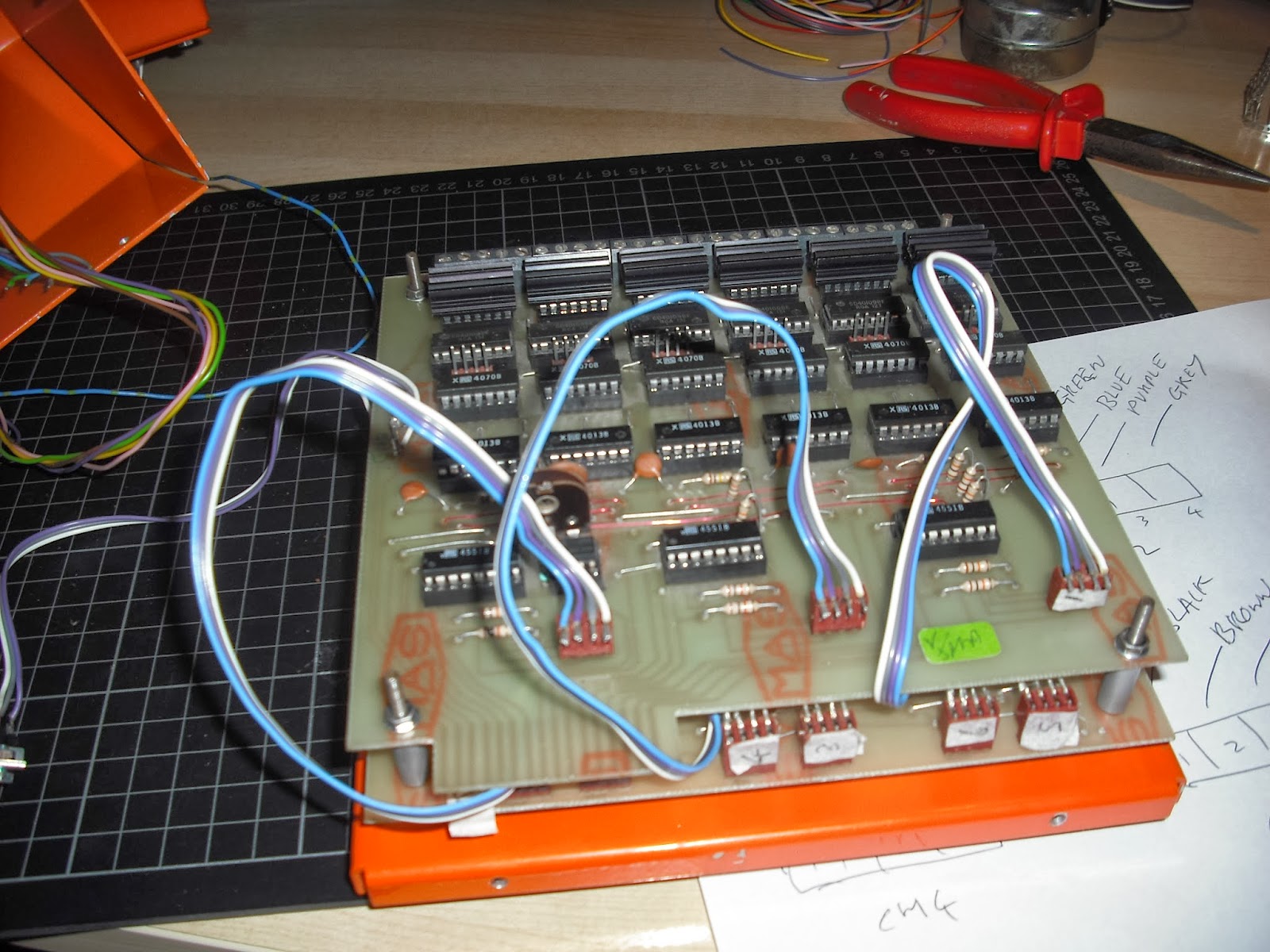
Finally, a photograph of the completed, and very much working Raspberry Pi / Arduino based Armdroid interface circuitry:

Saturday 8 March 2014

Final Assembly

This morning I started looking at what could possibly be causing tight spots on the upper-arm assembly.

Then suddenly spot luck (no pun intended)....  Picking up the assembly from the "donor" Armdroid, the shoulder spindle quite literally fell out.... On my other Armdroid, this was seized solid, and previously assumed this was meant to be fixed in place.  This made me wonder if this could be the cause of the problems....

The spindle i'm referring too is the one pictured below extruding from the large drive gears:
Colne Robotics part no. 117 (8mm x 95mm / tapped with M5 threads)


I decided to take the spindle out and have a closer look what's happening:


By using the spindle from the donor, this was driven into the shoulder by lightly tapping with a small hammer, pushing out the spindle.  The idea was to keep all the spaces in place and not loose anything in the process.

There was some light rust which was rubbed down with Wet & Dry, then lubricated with WD-40.   This was then tapped back into the shoulder and with a little persuasion this has freed up nicely.

After aligning the gearing, I slowly and carefully eased the assembly back into the shoulder:


At this point, before bolting everything tightly into place, I checked for tight spots, and so far, everything is running freely.  I carefully separated the drums with a small screwdriver and squirted oil with my precision oiler between all drums/spaces/bushes.

Without power applied to the motors, it's very easy to manually articulate the arm checking for tight-spots.


Sweet... No tight spots, and no "clunks" coming from the gearing...  Things are starting to look promising!

I cannot recommend enough doing this yourself, if you have any problems with the upper arm movements on your Armdroid. If you don't have a spare spindle, any M8 bolt of sufficient length could be used to drive out your spindle.

All that's left to do now, is re-string the broken finger cable, and finally tighten and tension all controls...

When it comes to re-stringing, the best advice I can give is follow the blueprints.  Study the diagrams until you understand what string goes over or under each of the pulleys.

I popped down to my local Staples and asked them to print the blue-prints on A2 drawing size.  I found this made following the string routing much easier on the eyes.

You will need a very sharp pair of scissors to cut the Kevlar - you'll never believe it, but since last summer our best pair was struggling to make decent cuts without frying the ends.   Another tip - a very good pair of steal tweezers, the type surgeons use, and you'll have no problems at all, but be warned....   you need lots of patience, restringing an Armdroid is not the most pleasant of jobs.

Bull dog-style clips come in very handy....


The excess string will be left until final adjustments have been made.... but this just about completes all the mechanical work....

Roll on next weekend, and we'll see how this performs at the Peterborough Raspberry Jam.   I will be demonstrating the Armdroid at the Show & Tell.   That said, I had better blow the dust of my Raspberry Pi and start work making the Pi tell the Arduino what to do.....

Friday 7 March 2014

Drive Shaft Replacement

Today, I have been busy replacing the main drive shaft and reduction gearing....

I started by scavenging parts from the "donor" Armdroid....   I'm interested to see if the reduction gearing is in better condition than on my other Armdroid, so these were extracted, after removing the arm from the shoulder:


Nothing much left here now - motor pulleys have also now been removed for spare parts:


After a quick inspection, only two have hairline fractures, and none have splits extending to the edges, which is good news.  I'm going to use them all, but will swap those with hairline fractures to drive the wrist actions - this leaves the pulleys in absolute best condition to drive the shoulder and elbow joints.

I also made a last minute decision to reuse the drive shaft as this appeared in slightly better condition than my original.


The pulleys cleaned up very well - after trying various cleaning products, I found Lemon Cream Cleaner (what you use in your kitchen) worked best, and as an added bonus, they all smell rather nice!

After installing into my Armdroid, I thought it would be a good idea to perform another bench test, and see if this has made any difference to the performance.   Yes!  Things have certainly improved, and that "clunking" problem seems to have been solved.

When fitting belts, they should be placed fully on the motor spindle and worked gently onto the reduction gearing.

I also took the opportunity whist the arm is out of the shoulder to run plenty of WD-40 onto the drive shaft and started lubricating the spur gears for re-assembly of the arm.   Using my precision oiler, I managed to run plenty of oil onto the roller bearings and swung the entire arm assembly around 360 degrees to ensure everything was coated well.


Another thing was to pull on the motor end-floats and lightly lubricated around the pulleys and motor spindles.

Next, installing the interface board back into the base:


I soldered up a new power connector - not pictured, although you can see the chassis socket has been re-installed in the next photograph:


All motor channels plugged in following the suggest motor/function assignments:

CHANNEL
FUNCTION
1
GRIPPER
2
LEFT WRIST
3
RIGHT WRIST
4
FOREARM
5
SHOULDER
6
BASE

After bolting the base plate back in, one last bench test to verify all motor channels are still running.  It took some gentile persuasion to get the board along with all the wiring into position.


At this point - the base of the Armdroid is in super running condition.  Tomorrow, I will remounting the arm, possibly this might require re-stringing.   Once of the problems I've been suffering is an excessive tight spot on the shoulder & forearm joints.  I'm wondering if in my previous attempt to restring the arm, I over-tensioned some of the cables, and is causing too much friction.

Something else I recently noticed on my Armdroid, the finger terminating cable clamps are worn/damaged. This might actually be the reason why a string broke back in December.

I was curious how these fingers come to bits, but after trying with several different pairs of circlip pliers, I just can't find anything that fits these small circlips:


I popped down to a local Model Shop in Milton Keynes, and the guy in the store was also stumped as what to suggest.  So, I am on the lookout for an extremely high quality set of mini circlip pliers, and this job will just have to wait for another time.

Tuesday 4 March 2014

Interface RetroFit

I've been in a panic to get things ready for the forthcoming Raspberry Jam in Peterborough.  So, what did I do this past weekend....  Take the whole thing to bits, of course....

I wanted to swap the interface driver boards, unfortunately this wasn't so simple, and required delicate key hole surgery.


The challenge was removing the awkward cable tie securing the wiring inside the bearing assembly.   You can just about make this out in the pictures below:


The power connections made by soldering directly to the board had to be removed, along with the 7805 power regulator bolted to the chassis.

Next, the stepper motor wiring was disconnected.  These terminal blocks are over 30 years old, needless to say, most of the terminals had rusted/seized solid.

The following table shows the stepper motor connections for this type of interface - included for my own reference:

TERMINAL
FUNCTION
CHANNEL #
RIBBON CABLE
1
+12 V

YELLOW / WHITE
2
Qa
1
BLACK
3
Qc
1
BROWN
4
Qb
1
RED
5
Qd
1
ORANGE
6
Qa
2
GREEN
7
Qc
2
BLUE
8
Qb
2
PURPLE
9
Qd
2
GREY
10
Qa
3
GREEN
11
Qc
3
BLUE
12
Qb
3
PURPLE
13
Qd
3
GREY
14
Qa
4
BLACK
15
Qc
4
BROWN
16
Qb
4
RED
17
Qd
4
ORANGE
18
Qa
5
BLACK
19
Qc
5
BROWN
20
Qb
5
RED
21
Qd
5
ORANGE
22
Qa
6
GREEN
23
Qc
6
BLUE
24
Qb
6
PURPLE
25
Qd
6
GREY

The micro-switch sensors feed into the lower interface board, so, before removing anything else, I separated the two boards and disconnect them.  I  completely removed the wiring loom, as I'm currently not making any use of it.

Finally, the prototype interface board is freed:


In order to connect the steppers to the new interface board, I soldered up connectors (see Testing a Stepper Motor for wiring details) and inserted in no particular order for testing purposes:


The heat-shrinking annoyed Yulia.  She'd been waiting all morning to wash her hair, and I was busy using the hairdryer !

Final bench test of the new interface board:


All motors were tested independently using the Arduino controller.  Eventually, I started issuing commands to drive multiple motors, and in different directions.  I carefully tested the base motor ensuring I wasn't tearing any cables!

 A short video showing 5 motor channels spinning simultaneously:


There is no need to worry about the alignment of the timing belts when testing the Armdroid this way - the 108T reduction gears would normally prevent excessive movement of gearing on the drive shaft.

Believe it or not, I managed to spin all 5 motors over 100RPM.  I will be doing further research driving motors at higher speeds, but I will need to rewrite my Arduino software at a lower-level to get major performance improvements.   Of course, higher speeds results in reduced torque, a side-effect of stepper motors.

I do however have some "clunks" happening at regular intervals.  This might be a consequence of the fractured pulleys, as I now have replacements, I will replace these and see if this makes any difference.