Today, bought a couple of terminal blocks which will be used to extend all stepper motor cables, and that will allow me to run with circuit boards outside of the base unit. Only then, can I start debugging my interface circuity...
Meanwhile.... Rudi Niemeijer from the Netherlands, has also been busy hooking up an Arduino to his Armdroid clone, and seems to be experiencing similar motor addressing problems....
http://www.rudiniemeijer.nl/ort-robotic-arm/
http://www.rudiniemeijer.nl/714/
(you'll need to Google Translate these pages from Dutch)
Update: new English pages are being maintained here
http://www.rudiniemeijer.nl/concorde-robotique-ort-robotic-arm/
Even though Rudi has a newer single interface board, the motor address logic is however roughly the same to the prototype models.
My current thinking on the addressing problems :
Motor addresses are decoded by IC6 74LS138 which selects one of eight possible outputs given an address from the interface port. We know only six (001 - 110) of these outputs are actually used, the others are not connected. The outputs of IC6 selects IC7 - IC12 which are 74LS175 (quad D flip-flops) used to latch the data bits.
This week... I'll be checking these addresses are correctly selecting these flip-flops. It's quite possible the MSB (most significant bit) of the Address is not as expected, and the bit pattern needs re-arranging to suit. But, I've not seen any examples on the internet of controlling software doing this! Of course, another potential problem would be address lines not running in order.
The next area where the addressing can be muddled up - and only applies to the prototype variants is the wiring of the PCB interconnects. Which is the routing from IC7 - IC12 on the interface PCB to the jumpers C1 - C12 which represent the motor drive channels for motors 1 - 6.
Finally, the physical connection of these motor channels to stepper motors assignments is another area to check.
Could be more involved... but I'll start with the above checklist....
Monday, 28 October 2013
Friday, 25 October 2013
RPi Interfacing
Progress report on the Raspberry Pi computer control & software.

A couple of evenings ago, decided to bite the bullet, and power up the Armdroid connected to my Raspberry Pi.
Needless to say, nothing happened... but I could hear a slight clunk coming from one of the stepper motors.
Eventually, I realized everything was working, but my delay statements was initially so large, it was taking minutes just to crank a few rotations. I gradually reduced the pulse delays to approx 500 milliseconds.
The motor addressing is a bit weird.....
Selecting motor 1, results in motor 5 spinning into life, etc. I spent hours double checking everything, and so far, my only conclusion is that the fly leads connecting the Armdroid's interface PCB to the driver PCB is mixing up the address selection. A couple of months ago I traced the entire interface board and was pretty happy I knew what to expect here, so I don't think the issue is with the software or that part of the interface circuity.
I really need to run everything with the board outside of the base, but to do that, I'll have to extend my motor cables and modify the power connections. Hopefully, I can then probe away with my Logic Probe on the running circuit to see what's happening.

Anyway, here is an example of my test program written in "C" :
Very much work in progress, so might not be the final cut, just yet ! The pulse delay of 500 milliseconds is still very slow, but this is good enough for debugging.
Having written this simple test program for 'prototype' variants, I fancy writing another version for Direct-Drive models. Only the implementation of drive_motor() will need to change, but, at the moment, I wont be in a position to test it.
I'll be adding the code to the resource page just as soon as I've figured out the best way to share files with eBlogger.

A couple of evenings ago, decided to bite the bullet, and power up the Armdroid connected to my Raspberry Pi.
Needless to say, nothing happened... but I could hear a slight clunk coming from one of the stepper motors.
Eventually, I realized everything was working, but my delay statements was initially so large, it was taking minutes just to crank a few rotations. I gradually reduced the pulse delays to approx 500 milliseconds.
The motor addressing is a bit weird.....
Selecting motor 1, results in motor 5 spinning into life, etc. I spent hours double checking everything, and so far, my only conclusion is that the fly leads connecting the Armdroid's interface PCB to the driver PCB is mixing up the address selection. A couple of months ago I traced the entire interface board and was pretty happy I knew what to expect here, so I don't think the issue is with the software or that part of the interface circuity.
I really need to run everything with the board outside of the base, but to do that, I'll have to extend my motor cables and modify the power connections. Hopefully, I can then probe away with my Logic Probe on the running circuit to see what's happening.

Anyway, here is an example of my test program written in "C" :
 /*
  * ArmTest.c: Armdroid Test
  *
  * Copyright (C) Richard Morris 2013 - http://armdroid1.blogspot.co.uk
  ***********************************************************************
  *
  */

 #include <stdio.h>
 #include <wiringPi.h>


 //// interface definitions ////

 #define SYNC        0x01            // sync - output Low / input High
 #define CDIR        0x10            // motor direction
 #define CCLK        0x20            // clock driver circuitry

 #define PULSE_DELAY    500                // delay in milliseconds


 void setup()
 {
   wiringPiSetup();

   // set pins 0-7 as outputs
   int pin;
   for (pin = 0; pin < 8; pin++)
   {
     pinMode( pin, OUTPUT );
   }

   // set Armdroid initially to input mode
   digitalWriteByte( SYNC );
 }

 void drive_motor( int mtr, int steps, int dir )
 {
   if (mtr < 1 || mtr > 6)            // check motor number in range
     return;
   if (steps <= 0)                    // no steps, nothing more to do
     return;
   if (dir < 0 || dir > 1)            // check direction flag
     return;

     // construct control byte
   // shift motor address into correct position
   // add SYNC and CLCK bits
   int output = CCLK + (mtr << 1) + SYNC;

   // add direction bit if necessary
   if (dir == 1)
   {
         output += CDIR;
   }

   int i;
   for (i = 0; i < steps * 2; i++)
   {
     // output control byte, and delay
     digitalWriteByte( output );
     digitalWriteByte( output-SYNC );
     delay( PULSE_DELAY );

     // output again with sync bit - returns to input mode
     digitalWriteByte( output );

     // toggle clock-bit to generate next pulse
     output = output ^ CCLK;
   }
 }

 int main()
 {
   int motor, steps, direction;

   setup();
   printf( "Raspberry Pi - ARMDROID TEST\n" );

   for (;;)    /* repeat forever */
   {
     printf( "Enter motor number (1 - 6) ? " );
     scanf( "%d", &motor );
     printf( "Enter steps ? " );
     scanf( "%d", &steps );
     printf( "Enter direction (0 = clockwise, 1 = counter-clockwise) ? " );
     scanf( "%d", &direction );

     drive_motor( motor, steps, direction );
   }
   return 0;
 }
Very much work in progress, so might not be the final cut, just yet ! The pulse delay of 500 milliseconds is still very slow, but this is good enough for debugging.
Having written this simple test program for 'prototype' variants, I fancy writing another version for Direct-Drive models. Only the implementation of drive_motor() will need to change, but, at the moment, I wont be in a position to test it.
I'll be adding the code to the resource page just as soon as I've figured out the best way to share files with eBlogger.
Sunday, 13 October 2013
RPi Interface - completed
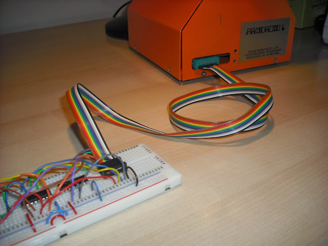
Today... Assembled my interface cable allowing connection from the Raspberry Pi interface circuitry to the Armdroid's parallel interface port:

Here's how this was assembled.....
Firstly, solder up the 10-way ribbon cable to a 20-way card edge connector - we only need to use one side as follows:

The other end is terminated with a 2x5 ribbon crimped connector:

To crimp, you need plenty of pressure... But, you don't want to damage the pins in doing so....
I sacrificed an IC socket by removing the pins, inserted the crimp connector into the shell of this IC socket which protects the pins, inserted the ribbon cable, and pushed together using a clamp like this....


A small G-style Clamp would also do the trick, except I couldn't find one in my garage!
Now, we're ready to install onto the interface circuit:

Minor wiring rearrangements made to route correct cables through to the ribbon cable. I have also coupled up the ground line (black) to the ground power rail on the breadboard. The +5volts (white) power line from the Armdroid is left unconnected:

You'll notice that when I constructed the circuit last week, I adopted the colour coding of my wiring based on the ribbon cable, which should simplify troubleshooting.
Finally, one last check with the multimeter checking we're not dropping resistance, and verify continuity. Then tested the whole circuit again with the Digital Logic Probe:

The completed interface:

Wednesday, 9 October 2013
RPi GPIO & Armdroid Interface
GPIO stands for General Purpose Input/Output, and a GPIO pin can be set to logic high, or low, with a value of 1 or 0 respectively. The Raspberry Pi can set pins to take either value and treat them as output, or it can detect a value as input.
The GPIO header on the Raspberry Pi consists of twenty-six pins, which include power (3.3v/5v/ground) and seventeen GPIO pins. Some of these pins have special functions as well, we won't concern ourselves with these for now.
The GPIO pins operate at 3.3volts, which means we need to do some logic-level translation in order to interface our Armdroid.
To make the make the task of breaking out the GPIO pins easier on a breadboard, I'm going to use an Adafruit Pi Cobbler breakout kit. I soldered up mine in about 10 minutes, but looks like you can now buy these ready assembled.
The layout of my Armdroid / Raspberry Pi interface circuit.

IC1 & IC2 are 74HC4050 High Speed Hex non-Inverting Buffers
The header pins (see right-hand side) represent the Armdroid connector D1 - D8
Power is taken directly from the GPIO, we could use the power source from the Armdroid interface
The circuit works using two 74HC4050 as logic level translators, converting logic high 3.3v to 5v before continuing to the Armdroid's 8-bit Parallel Interface. This design is not bi-directional, which means we cannot read the micro-switch sensors, but we'll revisit that later in time...
GPIO ASSIGNMENTS
PIN GPIO ARMDROID
11 0 (brown) D1
12 1 (red) D2
13 2 (orange) D3
15 3 (yellow) D4
16 4 (green) D5
18 5 (blue) D6
22 6 (purple) D7
7 7 (grey) D8
This table gives the physical pin numbers of each GPIO channel and mapping to Armdroid notation.
The completed circuit on the breadboard:


Testing
As mentioned in recent updates, the gpio command-line utility can be used to test the circuit. The following example sets pin 0 to output mode, and then sets to logic High.


All that I need to do now is solder up my ribbon cable and connectors.... and work can commence on writing software....
The GPIO header on the Raspberry Pi consists of twenty-six pins, which include power (3.3v/5v/ground) and seventeen GPIO pins. Some of these pins have special functions as well, we won't concern ourselves with these for now.
The GPIO pins operate at 3.3volts, which means we need to do some logic-level translation in order to interface our Armdroid.
To make the make the task of breaking out the GPIO pins easier on a breadboard, I'm going to use an Adafruit Pi Cobbler breakout kit. I soldered up mine in about 10 minutes, but looks like you can now buy these ready assembled.
The layout of my Armdroid / Raspberry Pi interface circuit.

IC1 & IC2 are 74HC4050 High Speed Hex non-Inverting Buffers
The header pins (see right-hand side) represent the Armdroid connector D1 - D8
Power is taken directly from the GPIO, we could use the power source from the Armdroid interface
The circuit works using two 74HC4050 as logic level translators, converting logic high 3.3v to 5v before continuing to the Armdroid's 8-bit Parallel Interface. This design is not bi-directional, which means we cannot read the micro-switch sensors, but we'll revisit that later in time...
GPIO ASSIGNMENTS
PIN GPIO ARMDROID
11 0 (brown) D1
12 1 (red) D2
13 2 (orange) D3
15 3 (yellow) D4
16 4 (green) D5
18 5 (blue) D6
22 6 (purple) D7
7 7 (grey) D8
This table gives the physical pin numbers of each GPIO channel and mapping to Armdroid notation.
The completed circuit on the breadboard:


Testing
As mentioned in recent updates, the gpio command-line utility can be used to test the circuit. The following example sets pin 0 to output mode, and then sets to logic High.
gpio mode 0 out
gpio write 0 1
By substituting pin numbers, we can test all 8 output lines on our circuit with a Digital Logic Probe


All that I need to do now is solder up my ribbon cable and connectors.... and work can commence on writing software....
Monday, 7 October 2013
Motor Assignments
Eagle-eyed readers may have noticed an 'oddity' with my stepper motor numbering in previous photographs, and why these did not resemble the suggested assignments in the construction guide....
When starting this project, I simply gave each motor an arbitrary number as parts was bagged up for safe keeping during disassembly. Later, having discovered my motor connections was in fact following the suggested assignments, I completely forgot to update the labels....
So, avoiding further confusion... at least for myself... here are two photographs showing the official motor numbering and function assignments:
I'll be relabeling my hand controller to match, all of this should make things easier to use next time!
Actually, it's a pity the original manual never included a diagram of motor assignments on the arm - I think it would have made visualizing this a hell lot easier !
Tomorrow.... An introduction to the Raspberry Pi's General Purpose Input Output (GPIO) facilities, and we'll discuss Armdroid interfacing.
When starting this project, I simply gave each motor an arbitrary number as parts was bagged up for safe keeping during disassembly. Later, having discovered my motor connections was in fact following the suggested assignments, I completely forgot to update the labels....
So, avoiding further confusion... at least for myself... here are two photographs showing the official motor numbering and function assignments:
 |
| Gripper (Motor 1), Left Wrist (2), and Elbow (4) |
 |
| Right Wrist (3) , Shoulder (5) and finally the obscured Base (6) |
Actually, it's a pity the original manual never included a diagram of motor assignments on the arm - I think it would have made visualizing this a hell lot easier !
Tomorrow.... An introduction to the Raspberry Pi's General Purpose Input Output (GPIO) facilities, and we'll discuss Armdroid interfacing.
Sunday, 6 October 2013
Raspberry Pi Setup
A couple of weekends ago I installed Raspbian in preparation for work on computer control aspect of the project. Raspbian is an optimized port of Debian Wheezy for the Raspberry Pi. I've also setup a complete development environment to write applications in native C, C++ and embedded JAVA.
This update explains how this was done...

Installing Raspbian was surprisingly straight forward. The same sd-card imaging technique used to install RISC OS was followed here.
I think the Software Configuration Tool started automatically on first boot, although it can be run anytime by typing: sudo raspi-config

Expanding the Filesystem ensures all available space on the SD card is used by the root partition. I would recommend this is done; a reboot is required. Also, don't forget to configure your keyboard, timezone, and networking settings. After which, the system will be ready for use....

This picture shows the standard X desktop running. I configured mine to always boot to Desktop.
I would highly recommended before doing anything else at this point - update your operating system:
After updating the operating system, I installed a SAMBA server allowing files to be shared between Windows. Other tools you might consider installing on your Windows clients are Putty, and WinSCP.
Useful Links
http://www.raspberrypi.org/
http://www.debian.org/
http://forums.debian.net/
http://www.linux.org/
Development Tools
The GCC C compiler is already included and installed with Raspbian.
Installed the following third party libraries which will be potentially useful (following the installation instructions on each site):
Both of these libraries are GPIO access libraries written in C for the BCM2835 used in the Raspberry Pi. WiringPi includes a handy command-line utility gpio which can be used to program and setup the IO pins - very useful for testing!
I'm still looking for a decent text editor (please don't suggest vi), but in the meantime I'll probably write my code on Windows, then copy and compile on the device.
JAVA
You might actually be wondering why... why Java ? After we have written some basic Armdroid test programs in C/C++, the first major project of this site will be constructing a web-based control solution. We'll be implementing this software in Java, to be hosted in a Java based Application Server.
I happened to find this blog article https://blogs.oracle.com/hinkmond/entry/quickie_guide_getting_hard_float which explains how to setup an Early Access Oracle JDK 8 on the Raspberry Pi.
In case your wondering what all this Hard Float and Soft Float is all about.... Earlier this year, Raspbian was available in two flavors - with hardware or soft-floating point number support. At the time, the available JVMs only supported the software floating point, so if you intended to use Java, you needed to install that variant of the operating system. The article above posted last December introduced the Early Access Release of the Oracle JDK running on hard float editions. A couple of months ago, it would seem the Raspberry Pi Foundation dropped all support for the soft-float images, and now, you can only download and install the hard float images...
I downloaded the JDK 8, then compiled & ran HelloWorld.java to prove everything is working correctly.
Finally, I installed the Pi4J library which simplifies controlling the GPIO port from a java application.
I ran the included sample programs to check everything was working using my Logic Probe to prove the pins are changing state high to low, etc.
- update -
Since setting up my Raspberry Pi, the foundation posted this article last week http://www.raspberrypi.org/archives/4920 announcing future releases of Raspbian will include Oracle Java; existing users can install it by typing:
sudo apt-get update && sudo apt-get install oracle-java7-jdk
This update explains how this was done...

Installing Raspbian was surprisingly straight forward. The same sd-card imaging technique used to install RISC OS was followed here.
I think the Software Configuration Tool started automatically on first boot, although it can be run anytime by typing: sudo raspi-config

Expanding the Filesystem ensures all available space on the SD card is used by the root partition. I would recommend this is done; a reboot is required. Also, don't forget to configure your keyboard, timezone, and networking settings. After which, the system will be ready for use....

This picture shows the standard X desktop running. I configured mine to always boot to Desktop.
I would highly recommended before doing anything else at this point - update your operating system:
- Double click LXTerminal to get a command prompt
- sudo apt-get update
- sudo apt-get install
After updating the operating system, I installed a SAMBA server allowing files to be shared between Windows. Other tools you might consider installing on your Windows clients are Putty, and WinSCP.
Useful Links
http://www.raspberrypi.org/
http://www.debian.org/
http://forums.debian.net/
http://www.linux.org/
Development Tools
The GCC C compiler is already included and installed with Raspbian.
Installed the following third party libraries which will be potentially useful (following the installation instructions on each site):
Both of these libraries are GPIO access libraries written in C for the BCM2835 used in the Raspberry Pi. WiringPi includes a handy command-line utility gpio which can be used to program and setup the IO pins - very useful for testing!
I'm still looking for a decent text editor (please don't suggest vi), but in the meantime I'll probably write my code on Windows, then copy and compile on the device.
JAVA
You might actually be wondering why... why Java ? After we have written some basic Armdroid test programs in C/C++, the first major project of this site will be constructing a web-based control solution. We'll be implementing this software in Java, to be hosted in a Java based Application Server.
I happened to find this blog article https://blogs.oracle.com/hinkmond/entry/quickie_guide_getting_hard_float which explains how to setup an Early Access Oracle JDK 8 on the Raspberry Pi.
In case your wondering what all this Hard Float and Soft Float is all about.... Earlier this year, Raspbian was available in two flavors - with hardware or soft-floating point number support. At the time, the available JVMs only supported the software floating point, so if you intended to use Java, you needed to install that variant of the operating system. The article above posted last December introduced the Early Access Release of the Oracle JDK running on hard float editions. A couple of months ago, it would seem the Raspberry Pi Foundation dropped all support for the soft-float images, and now, you can only download and install the hard float images...
I downloaded the JDK 8, then compiled & ran HelloWorld.java to prove everything is working correctly.
Finally, I installed the Pi4J library which simplifies controlling the GPIO port from a java application.
I ran the included sample programs to check everything was working using my Logic Probe to prove the pins are changing state high to low, etc.
- update -
Since setting up my Raspberry Pi, the foundation posted this article last week http://www.raspberrypi.org/archives/4920 announcing future releases of Raspbian will include Oracle Java; existing users can install it by typing:
sudo apt-get update && sudo apt-get install oracle-java7-jdk
Saturday, 5 October 2013
Bench Test (No. 2)
This morning I opened up the base again to retrieve a lost nut that accidentally dropped in the other weekend back...
 With the circuit board exposed, I happened to notice one of the links touching another component.... I re-positioned the link wire, and guess what.... The link was feeding into the direction control logic for the gripper stepper motor. Hopefully a slight tweak was all that's needed to fix the problem!

The blueprints included flat washers on the PCB mounts which I added as mine was missing these...

I know... I've had bad experiences following the blueprints to the letter, but in this case, I see no reason why these washers would not help spread the load from the fastenings. They are M3 flat washers, purchased from a local model shop.
Finally, I could replace the missing bolt on the side plate having retrieved that wild nut...

Connected the hand controller and powered up with my new power supply for bench testing....
A couple of video clips, firstly, the Gripper action now working:
In this clip - you'll see a problem with the Shoulder and Upper arms having tight spots causing a lot of judder. I can see we're rubbing on the side plates at times, but I need to look at this again with fresh eyes to figure out what to do about it....
So, re-positioning that link certainly solved the problem with the direction control. I don't really like these circuit boards with unshielded links running everywhere, if you have any problems in this area, I would recommend checking your not touching any neighboring components.
On the whole, I would say we're making good progress.
I'm still missing a few fastenings, so another weekend I intend to pop to a local Nut & Bolt stockist to remedy that situation.
Not a bad pose in these pictures...


 With the circuit board exposed, I happened to notice one of the links touching another component.... I re-positioned the link wire, and guess what.... The link was feeding into the direction control logic for the gripper stepper motor. Hopefully a slight tweak was all that's needed to fix the problem!
The blueprints included flat washers on the PCB mounts which I added as mine was missing these...

I know... I've had bad experiences following the blueprints to the letter, but in this case, I see no reason why these washers would not help spread the load from the fastenings. They are M3 flat washers, purchased from a local model shop.
Finally, I could replace the missing bolt on the side plate having retrieved that wild nut...

Connected the hand controller and powered up with my new power supply for bench testing....
A couple of video clips, firstly, the Gripper action now working:
In this clip - you'll see a problem with the Shoulder and Upper arms having tight spots causing a lot of judder. I can see we're rubbing on the side plates at times, but I need to look at this again with fresh eyes to figure out what to do about it....
So, re-positioning that link certainly solved the problem with the direction control. I don't really like these circuit boards with unshielded links running everywhere, if you have any problems in this area, I would recommend checking your not touching any neighboring components.
On the whole, I would say we're making good progress.
I'm still missing a few fastenings, so another weekend I intend to pop to a local Nut & Bolt stockist to remedy that situation.
Not a bad pose in these pictures...


Friday, 4 October 2013
MIT M-Blocks
I know, I know, my friends.... This has nothing whatsoever to do with Armdroids, but these self assembling cubes revealed today by MIT are totally awesome....
http://web.mit.edu/newsoffice/2013/simple-scheme-for-self-assembling-robots-1004.html
I have to say, I really am taken by the relative simplicity of their design.... They can flip, rotate, jump, and snap together, all by wireless computer control. It's really amazing to think in the 1980's the Armdroid seemed like technology that came straight out of Star Wars, and yet today.... we have these......


The BBC news website described these as having similarities to the 'Terminator' liquid steel which had the ability to form solid shapes.
I wounder if that will ever happen in my life time ?
One thing however that is on my mind is the concept of developing an open-source Humanoid Robot, using serial based digital servos, carbon fiber chassis for lightness & strength, maybe a Raspberry Pi as the main board.... Certainly has had my mind thinking about it as a potential next project.... After all, this is an area of robotics i'm rather passionate about!
Anyway, in the meantime, and a little more down to earth.... Armdroid.... A relatively simple job for the evening was dabbing the ends of the kevlar string using super glue as per the recommendation in the instructions to prevent the string from fraying. What worked best for me, was applying the glue using a fine modelling brush, as some of the strings are in pretty inaccessible places.
Thursday, 3 October 2013
Timeout
It feels like it's been a while, which it has ... Last month I was trying desperately to ready my Armdroid for the next Milton Keynes Raspberry Jam. This event, should have taken place on the last Sunday of the month, which unfortunately never happened.
An announcement was made on the forum discussing the future, attendances had been dropping, and could be closed down unless somebody is interesting in running the show... It would be a great shame for that to happen as Bletchley Park makes such a great venue. My next nearest jams are Oxford or Cambridge, so who knows, you might catch me attending in future!
In light of this, I decided to take a break for a couple of weeks from the project work, and catch up with other things around the house that had been neglected.
This weekend I'll be blogging about my Raspberry Pi Debian / development setup from a couple of weeks ago, and will start constructing the interface circuitry.
Focus over the forthcoming weeks/weekends will be exclusively centered around interfacing and computer control.
Talking of the Blog... It's really exciting to see more readers interacting with the site, and received some very encouraging feedback. I've now been linked from the excellent www.theoldrobots.com website which contains a wealth of Armdroid related information.
Subscribe to:
Posts (Atom)