My recently acquired Armdroid is a complete unknown - we have no idea of its working condition. This morning, I decided, in preparation for bench testing, making up a power supply connector would be a good starting point, then, checking we have a working stepper motor. Knowing we have a working stepper means we can eliminate that during our problem solving, especially if the interface board has issues.

A quick and dirty test uses an LED connected to any two inputs of the motor. By spinning the motor shaft by hand, electromagnetism causes electricity to be generated, and this can be seen by the LED flashing. Repeat for all other input terminals.
The more scientific approach is to measure the resistance between the center tap, and each motor coil input. This should be approximately 47 ohms per phase.
You can quickly get an idea of the working condition using either technique - in my case, this proved to be successful.
The steppers used in the Armdroid are the ID35 35014 types, originally manufactured by Philips. These motors consist of six connections, and are generally known as Unipolar Stepper Motors.
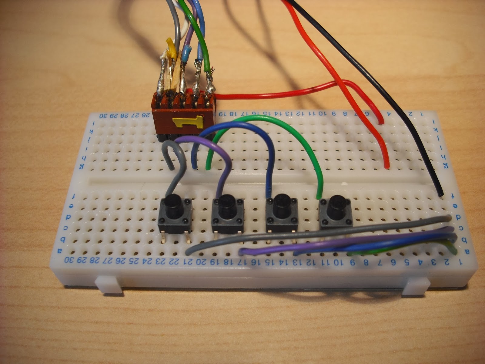
For readers new to the theory and operation of steppers, I quickly assembled the following circuit to demonstrate in a short video how they work manually....
This circuit follows the same wiring/colour scheme recommended by Colne Robotics:
You'll need +12v / +15v to power this circuit.
Pressing any of the four Tactile switches energizes the motor coils, and by carefully sequencing things, you can spin the motor. Remember, with these steppers, each step angle is 7.5 degrees, so it takes a while to complete one revolution. To rotate in the opposite direction, simply reverse this sequence.
You should monitor the current used when each coil is energized, which should be approx 0.24 Amps per phase. I had some inconsistent readings at first, which turned out to be a problem with the soldering of the connector/cabling causing a short on two pairs of wires. If you look closely at the connector in the picture, you can make out where the cables bypassing the interface circuit was made (see previous post).
To recap, motor connections are:
Qa Black or Green Qd | Qa
Qb Red or Purple ------+------
Qc Brown or Blue +15v - +15v
Qd Orange or Grey ------+------
+15v Yellow or White Qc | Qb
as viewed when the motor is orientated as follows:
The center taps are combined to a single +15 V supply, giving 5 connections per stepper motor.
The PCB connection uses a 5-way connector with the following pin-outs:
+15v | Qd | Qb | Qc | Qa
One last thing.... Never try connecting a stepper motor directly to a Raspberry Pi / Arduino without including suitable driver circuitry - otherwise you'll seriously damage the device. I might, when I have time, throw an example circuit together demonstrating how you would go about this using the ULN2003A Darlington Array.


No comments:
Post a Comment