Showing posts with label Arduino. Show all posts

Wednesday, 19 August 2015

I2C Port Expander

For all of my projects I have used the standard digital output pins when connecting to the Armdroid's 8-bit parallel interface.  But, what if you want to free up some of these pins in order to use external sensors, controls, or other devices...

The easiest way of getting more inputs and outputs is to use an "i/o port expander".  This is a device that allows you to control a number of ports using data sent to the device.  A port expander takes the data and controls the appropriate I/O pins.  This allows lots of sensors and devices, including the ability to control multiple Armdroids using only a few pins on the Arduino board.

The device I chose was the PCF8574A which has eight general purpose input/output pins controlled using I2C (pronounced I-squared-C).  I2C is a serial communications protocol allowing ICs to swap data on the same two-wire bus - Serial Data Line (SDA) and Serial Clock Line (SCL).

There are other devices available supporting 16 ports (eg. MCP23017), or SPI buses (eg. MCP23S17) and are similar in usage.  Although SPI (10Mhz) is faster than I2C (1.7MHz), for our purpose interfacing the Armdroid, it doesn't really make much difference

Pinouts

PCF8574A pinouts
The expanded I/O port are Pins 4-7 and 9-12 to be connected to the Armdroid interface D1-D8

Three address pins A0, A1, A3 determine the chips ID and must be wired to either +5v or GND.

Pin 13 (INT) used for interrupt output - leave disconnected for now

SDA - SDA pin on Arduino
SCL - SCL pin on Arduino
Vcc - +5v on Arduino
GND - GND on Arduino plus Armdroid interface GND

The 8574A can be assigned an address in the range 0x38-0x3F, and you can change this address by changing the connections of the pins A0, A1, and A2 as shown in the following table:

A0
A1
A2
Address
GND GND GND 0x38
+5V GND GND 0x39
GND +5V GND 0x3A
+5V +5V GND 0x3B
GND GND +5V 0x3C
+5V GND +5V 0x3D
+5V +5V GND 0x3E
+5V +5V +5V 0x3F

You can use up to eight of these PCF8574A chips on the same IC2 bus.  Texas Instruments also manufacture the PCF8574 (without the A), essentially the same device with addresses ranging from 0x20-0x27.

You might find this i2c_scanner_sketch useful to verify your I2C communication is working if you have any problems.

Circuit Diagram


Circuit diagram for 8-bit Armdroid interface with PCF8574A

PCF8574A / Armdroid 1 connections:

P0 (pin 4) - D2 (J1/pin 4)
P1 (pin 5) - D1 (J1/pin 3)
P2 (pin 6) - D4 (J1/pin 6)
P3 (pin 7) - D3 (J1/pin 5)
P4 (pin 9) - D6 (J1/pin 8)
P5 (pin 10) - D5 (J1/pin 7)
P6 (pin 11) - D8 (J1/pin 10)
P7 (pin 12) - D7 (J1/pin 9)

J1/pin 1 (+5v) - not connected
J1/pin 2 (Gnd) - Common Gnd (Arduino & PCF8574A)

The address of the PCF8574A is hard-coded to 0x38 by grounding A0, A1, and A2.  I would recommend starting with these settings until you have something working.

Code

Surprisingly, the code changes to support the port expander in the Armdroid Library are minimal thanks to C++ inheritance, and the Arduino 'Wire' library.

When designing the Armdroid library, flexibility was foremost, and it was always my intention to allow the library to be easily adapted for use in different projects.

To make this possible, core functionality was implemented in an abstract base class which can be derived into specialized classes.  This base class doesn't actually have any knowledge how control the hardware, rather, its up to the derived classes to implement that.  Another potential use in future might include supporting optimized versions for different Arduino boards.

In our case, we're creating a new class ArmdroidPortExp inheriting from ArmBase to represent our port expander variant:

 class ArmdroidPortExp : public ArmBase {  
  public:  
  void begin(uint8_t address = 0x38);  
  protected:  
  void armdroid_write(uint8_t output);  
  private:  
  uint8_t i2c_addr;  
 };  

This implementation adds a new member function ArmdroidPortExp::begin(uint8_t address) responsible for setting up the I2C hardware, and stores the supplied address of the port expander.  We also take the opportunity to initialize the Armdroid interface at this point.

The virtual function ArmdroidPortEx::armdroid_write(uint8_t output) simply writes a byte to the port expander using the address supplied earlier.  This is all done using the 'Wire' library that conveniently abstracts us from low-level I2C protocol/transmission details:

 void ArmdroidPortExp::begin(uint8_t address)  
 {  
  i2c_addr = address;  
  Wire.begin();  
  Wire.beginTransmission(i2c_addr);  
  Wire.write(STROBE);  
  Wire.endTransmission();  
 }  
 void ArmdroidPortExp::armdroid_write(uint8_t output)  
 {  
  Wire.beginTransmission(i2c_addr);  
  Wire.write(output);  
  Wire.endTransmission();  
 }  

The implementation really is that simple !

Finally, here's a snippet of code that instantiates and uses the newly derived class...

 #include <Wire.h>  
 #include "Armdroid.h"  
 #include "ArmdroidPortExp.h"  
 // port expander address:  
 const int i2c_addr = 0x38;  
 // initialize Armdroid library:  
 ArmdroidPortExp myArm;  
 void setup()  
 {   
  myArm.begin(i2c_addr);  
  myArm.setSpeed(120);  
  myArm.torqueMotors(true);  
 }  
 void loop()  
 {  
      .  
      .  
      .  
 }  

I've added this code as an extension to the Armdroid Library as a separate package:
https://github.com/Armdroid/Armdroid-Arduino-PortExp

It wasn't possible to add this code to the library without introducing a dependency on the Wire library due to an 'oddity' with the Arduino IDE build mechanism.  If you intend to make use of these extensions, you will need to first install the Armdroid-Arduino-Library, then follow the instructions to install Armdroid-Arduino-PortExp

Included with this library is a modified version of the AsyncDemo previously presented with the Asynchronous library enhancements.

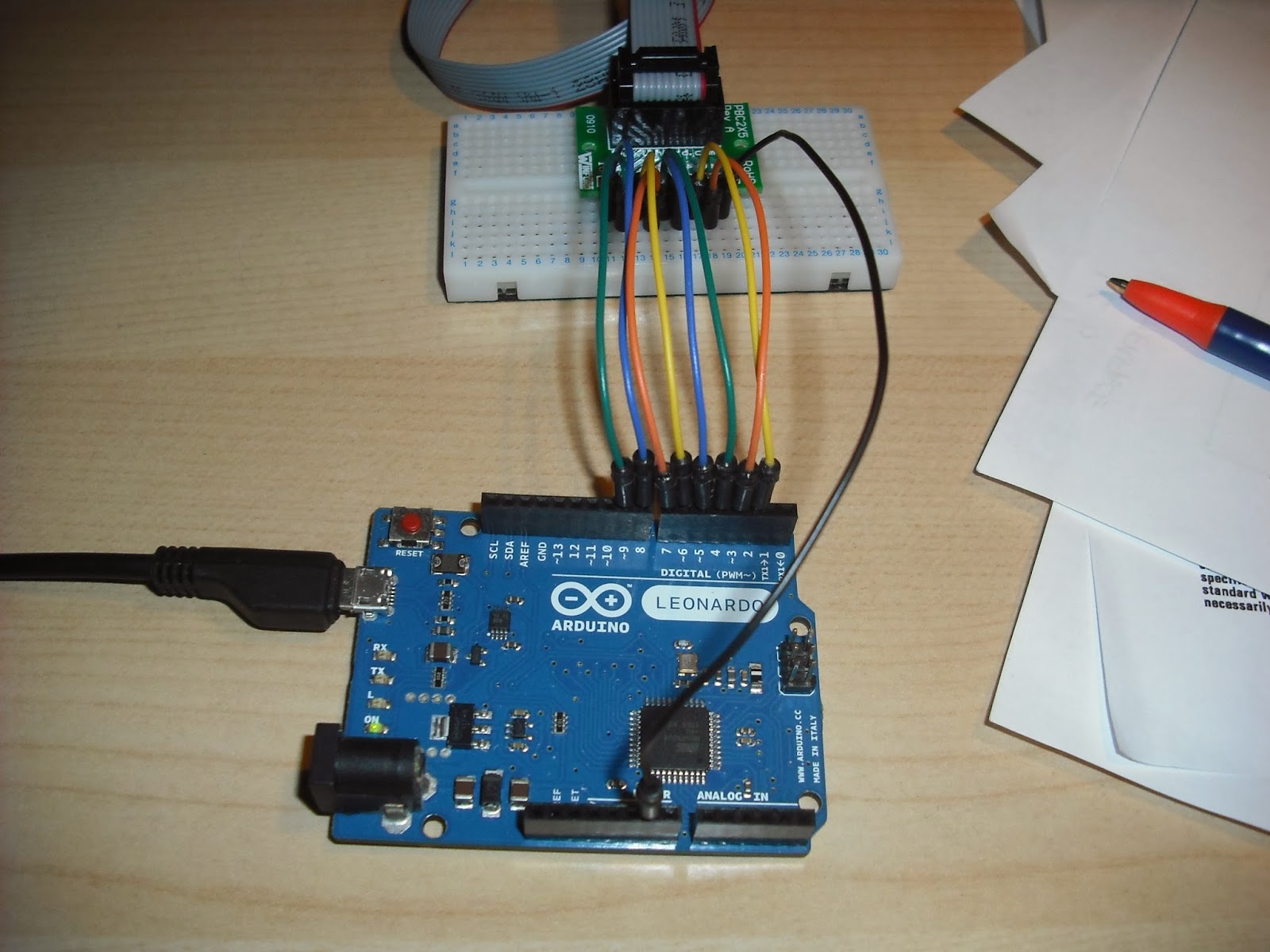
Photographs of my test circuit for reference:

See Also

PCF8574A data sheet: http://www.ti.com/lit/ds/symlink/pcf8574a.pdf
I2C tutorial: http://www.robot-electronics.co.uk/i2c-tutorial
Arduino wire library: https://www.arduino.cc/en/Reference/Wire

Standard Armdroid / Arduino wiring:
http://armdroid1.blogspot.co.uk/2014/02/interface-bench-test-part-1.html
http://armdroid1.blogspot.co.uk/2014/02/interface-bench-test-part-2_15.html
http://armdroid1.blogspot.co.uk/2014/02/interface-bench-test-part-3.html

Tuesday, 13 January 2015

Infrared Remote Control

I realise it's been a long time since writing anything here...

Today, I'm going to share with you my Armdroid Remote Controller project, which was quickly hacked together for demonstrating the Armdroid 1 during a recent meeting of volunteers at TNMOC.

The circuit makes use of a single TSOP4838 IR receiver module along with some rather cleaver programming that decodes key presses and operates various Armdroid functions.

I'll be including the source code for this project as an example sketch in the forthcoming release of Armdroid Library on GitHub.

The project works surprisingly well, although movements to preset positions are made point-2-point (P2P), which is slightly different to continuous path movements.  This is after all, a demonstration, although could be easily extended to support waypoints and recording/playback of movements.

I've been using an old Sky remote control handset, you'll need to change the scan codes to match your hardware, although instructions will be included how to do this.

Connecting an infrared receiver module is relatively simple, the sensor output is connected to a spare digital input on the microcontroller.

ArmdroidShield (version 1) utilizes pins 2-9 for connecting to the Armdroid's 8-bit parallel interface, so pin 10 was chosen for this purpose, along with +5V and Gnd connections.  There are many common IR receiver modules available.  Check the datasheet for your device to ensure that you connect it correctly.

The software works by decoding the IR signals to digital pulses that correspond to buttons on the remote.  A scan code lookup table is then used to assign Armdroid functions to key presses.   This table uses function pointers to simplify the program logic, also included are methods for Rolling/Pitching the Gripper, along with routines for calculating target offsets when moving to new positions.


Saturday, 15 November 2014

Arduino ArmdroidShield

The restoration of TNMOC's Armdroid is getting closer to completion, and attention has shifted towards designing suitable displays for the robot at the museum.

Initial displays are likely to be Arduino based, and in time, we'll probably add other historical computers into the mix.   In the meantime, something I had not given much thought about, was what to do with my 'temporary' breadboard interface that's been used over the past year, a more permanent solution is however needed.

So, a couple of weeks ago, I decided to design a PCB to be called.... wait for it.... ArmdroidShield !

Having a purpose made PCB will of course be more reliable, and better suited to a harsher museum environment.  The goal was to keep things flexible - perhaps we'll use these at a future Summer/Winter Bytes and students can design other Armdroid-based control systems, so making the board using a Shield design, was an obvious choice.

This was my first attempt at designing a double-sided PCB.  Fortunately, the design doesn't require many components, so from start to finish - 2hrs including inspection of final design, and correcting contacts positioned too close together.

The PCB arrived the following week directly from the fabricator, and as you can see the results are pretty good:

ARDUINO ArmdroidShield

The shield has been designed around the Arduino R3 header standard making it compatible with the following products:
  • Arduino Uno (Revision 3)
  • Arduino Leonardo
  • Arduino Yun
  • Arduino Ethernet
  • Arduino Tre & Arduino Zero (when available)
It's a very simple board, really just an adapter - only Digital Pins 2 through to 9 are utilized, along with common grounds.

The tricky bit was soldering the Stackable Headers and keeping everything properly aligned, but with perseverance, got there in the end.

ARDUINO ArmdroidShield

ArmdroidShield installed on the Arduino Leonardo:


Completed assembly ready for bench testing:


Tuesday, 25 March 2014

Armdroid Library

The software section has been just updated to include the newly released Armdroid Library and includes details of the GIT source repository.

The Armdroid Library has been developed especially with portability in mind, but at the moment, only Arduino is currently supported.  Hopefully this will change when support is added for other platforms and micro-controllers.

Summary of key library features:
  • Responsible for all low-level control & dynamics
  • Configurable which I/O pins are used for interface connections
  • Reusable class structure design
  • Drives single/multiple motors
  • Variable speed control
  • Maintains channel offset counters
  • Custom motor channel re-mapping (table driven)
  • Supports multiple addressing modes

The library includes examples, which also contains the slave Serial Driver uploaded to my Arduino Leonardo and demonstrated at UCP (see previous post) driven by a Raspberry Pi.   More example programs will be added, and I'll also be writing various Tutorials how to write your own programs, and build different interfacing circuits using this library.

The library currently supports different Armdroid models - this includes addressing modes for both "prototype" and "production" models with the single-interface boards.  Prototype variants will however need to be configured as Direct-Drive (see resources section for clarification).  By default, the library assumes your interfacing a production model; otherwise for prototype models, simply add #define INTERFACE_PROTOTYPE  before all include statements in your sketches.

Hopefully, owners wanting to experiment with interfacing their Armdroid to Arduino (and later Raspberry Pi) will be interested in this library, and all comments/suggestions for enhancements gratefully received.

That said...  I've also been receiving correspondence from people interested in controlling their Armdroid from IBM PC and compatibles.  Of course, Arduino is ideal for achieving this purpose, and is relatively inexpensive.  We can use USB/Serial connectivity to interface the device, and the same Serial Driver program included with the library can be used without modification.

Because of the amount of interest shown, a slight digression will include developing a variant of LEARN for Windows.  This will be followed with Tutorials how to install, and configure the software.

Wednesday, 12 March 2014

Connecting Raspberry Pi to Arduino using the Serial Port

This is certainly not the first Article explaining how to connect a Raspberry Pi to an Arduino using serial communications, but I wanted to share with you my experiences on this subject....

As my previous work with the Arduino has centered around serial communications, I wanted to use the hardware serial port on the Rapsberry Pi instead of using any USB ports.  I already have my keyboard & mouse plugged into these ports!


Starting with the Hardware


To safely connect the Raspberry Pi to an Arduino (or any native 5-Volt based microcontroller) using serial communications, you really should incorporate a logic-level shifter to ensure  the +5V will not harm the rather delicate Raspberry Pi, which of course is an unprotected, native +3.3V device:


Logic converter - Raspberry Pi feeds the low voltage (+3.3V) side, Arduino feeds into the higher (+5V) side:


These logic converters are generally bi-directional devices, and really do simplify voltage translations.  The one used here was produced by HobbyTronics in the UK, but Adafruit also manufacture an equivalent.

Both TX and RX lines are crossed over here - swapping the TX line from one, becomes the RX signal for the other device.

A close up of the Raspberry Pi serial connections - GPIO header pin 8 UART TX (yellow), GPIO header pin 10 UART RX (green), power 3.3V (red) and GND (black):


Arduino wiring - Digital Pin 0 RX (green), Digital Pin 1 TX (yellow) and power.  All other digital I/O pin connections are for the Armdroid 8-bit parallel interface:


I'll follow up with a schematic for the above, later, but I'm afraid, I simply don't have time at the moment as I'm trying to get everything ready for the Raspberry Jam on Saturday.


Software Configuration


With the hardware now sorted, you need to configure your Raspberry Pi to use the Serial Port in your own applications.

The reason for this is because by default, the serial port is used for Console Input/Output, and the kernel also sends diagnostic information to this port when booting the system.

To enable the serial port for your own use, you need to disable this by editing  /etc/inittab

Simply comment out (adding a # character to the beginning of the line):
T0:23:respawn:/sbin/getty -L ttyAMA0 115200 vt100

To look like:
#T0:23:respawn:/sbin/getty -L ttyAMA0 115200 vt100

Save the file.  The next step is optional, but i would recommend you do this otherwise the device connected to the other end of the serial port will receive startup information.

Edit the file  /boot/cmdline.txt

Locate the following line:
dwc_otg.lpm_enable=0 console=ttyAMA0,115200 kgdboc=ttyAMA0,115200 console=tty1 root=/dev/mmcblk0p2 rootfstype=ext4 elevator=deadline rootwait

And remove all references to ttyAMA0 (which is the name of the serial port device) to look like this:
dwc_otg.lpm_enable=0 console=tty1 root=/dev/mmcblk0p2 rootfstype=ext4 elevator=deadline rootwait

Save the changes, and reboot the system.


Testing


Normally, testing with minicom at this stage should result in your Raspberry Pi communicating with your connected serial device....  but this wasn't happening for me....  I checked the baud rate (9600) and all the other connection settings, but nothing made any difference.   Then, after carefully checking the wiring, which appeared to be good, I was well 'n truly stumped.

To install minicom if you don't already have it installed, its as simple as typing:
sudo apt-get install minicom

This can then be executed by the following command:
minicom -b 9600 -o -D /dev/ttyAMA0

All characters type will be transmitted to the serial port, and all characters received will be displayed on the terminal, type Ctrl+A and Q to finish.


So, after a couple of hours of probing with my logic probe and multimeter, I was really struggling to explain why my Arduino wasn't responding.   On one hand, I had an Arduino connected to my laptop, and that was working perfectly, and on the other, a Raspberry Pi which wasn't working.

I then started doubting my Raspberry Pi was functioning properly, so after convincing myself that I've blown up the GPIO port by earlier experiments, and without having a spare Pi at hand to test....   I Google'd  local suppliers from which I might be able to quickly purchase another Raspberry Pi.

My travels lead me to Cyntech Components, based locally in Milton Keynes:


Normally, they operate from an online store - if these guys didn't accept visitors, I was willing to beg, plead, do anything, to get my hands on another Raspberry Pi.   Fortunately, when I called them up, Dave (the proprietor) said no problems.... so off I jumped in the car and made a visit...

I purchased another Raspberry Pi Model B, and was also tempted into a few other accessories whilst I was there...


The packet in static sensitive bag is an add-on relay module, this will actually come very useful for something I have planned for later in the year - you will have to wait and see what that will be....   Anyway, Dave was very welcoming, so do give these guys a call if your needing accessories.

Once back home, I quickly swapped the Pis over, and guess what happened... still nothing!

I was now scratching my head....  Before giving up, and just heading down to the local boozer for the rest of the afternoon (I had the day off work you see)....  I suddenly ended up finding something on Arduino's website about the board I'm using, the Ardunio Leonardo

Arduino Leonardo - Product Overview

which says (see Input/Output section)  "Note that on the Leonardo, the Serial class refers to USB (CDC) communication; for TTL serial on pins 0 and 1, use the Serial1 class."

I then suddenly realized why transmitting over USB resulted in nothing being transmitted through the hardware serial port pins.   This Leonardo board must be slightly different to other models, and the USB port is treated completely differently to the hardware based serial port.   Doh !!!

Changing my program code on the Arduino to talk to Serial1 instead of Serial, and that resolved the problem....   So, there you go, moral of the story....  RTFM !!!   :-)


Finally, a photograph of the completed, and very much working Raspberry Pi / Arduino based Armdroid interface circuitry:

Tuesday, 4 March 2014

Interface RetroFit

I've been in a panic to get things ready for the forthcoming Raspberry Jam in Peterborough.  So, what did I do this past weekend....  Take the whole thing to bits, of course....

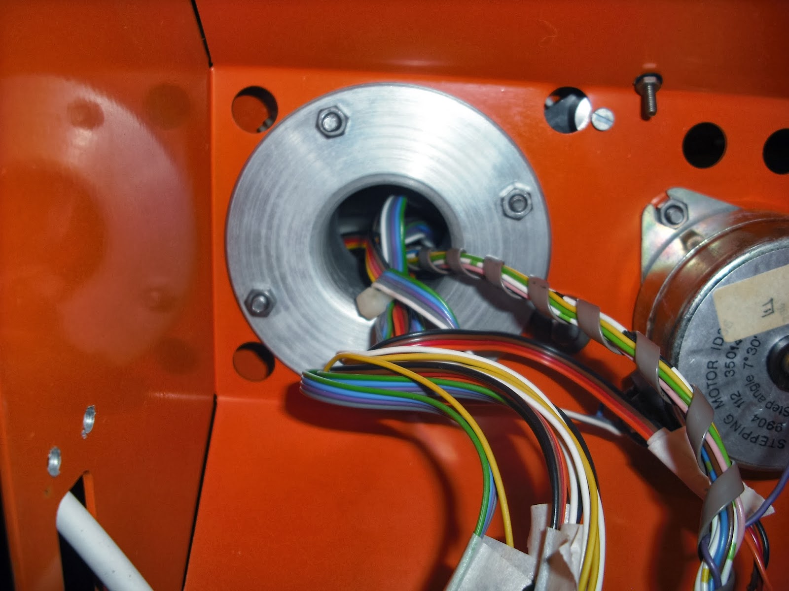
I wanted to swap the interface driver boards, unfortunately this wasn't so simple, and required delicate key hole surgery.


The challenge was removing the awkward cable tie securing the wiring inside the bearing assembly.   You can just about make this out in the pictures below:


The power connections made by soldering directly to the board had to be removed, along with the 7805 power regulator bolted to the chassis.

Next, the stepper motor wiring was disconnected.  These terminal blocks are over 30 years old, needless to say, most of the terminals had rusted/seized solid.

The following table shows the stepper motor connections for this type of interface - included for my own reference:

TERMINAL
FUNCTION
CHANNEL #
RIBBON CABLE
1
+12 V

YELLOW / WHITE
2
Qa
1
BLACK
3
Qc
1
BROWN
4
Qb
1
RED
5
Qd
1
ORANGE
6
Qa
2
GREEN
7
Qc
2
BLUE
8
Qb
2
PURPLE
9
Qd
2
GREY
10
Qa
3
GREEN
11
Qc
3
BLUE
12
Qb
3
PURPLE
13
Qd
3
GREY
14
Qa
4
BLACK
15
Qc
4
BROWN
16
Qb
4
RED
17
Qd
4
ORANGE
18
Qa
5
BLACK
19
Qc
5
BROWN
20
Qb
5
RED
21
Qd
5
ORANGE
22
Qa
6
GREEN
23
Qc
6
BLUE
24
Qb
6
PURPLE
25
Qd
6
GREY

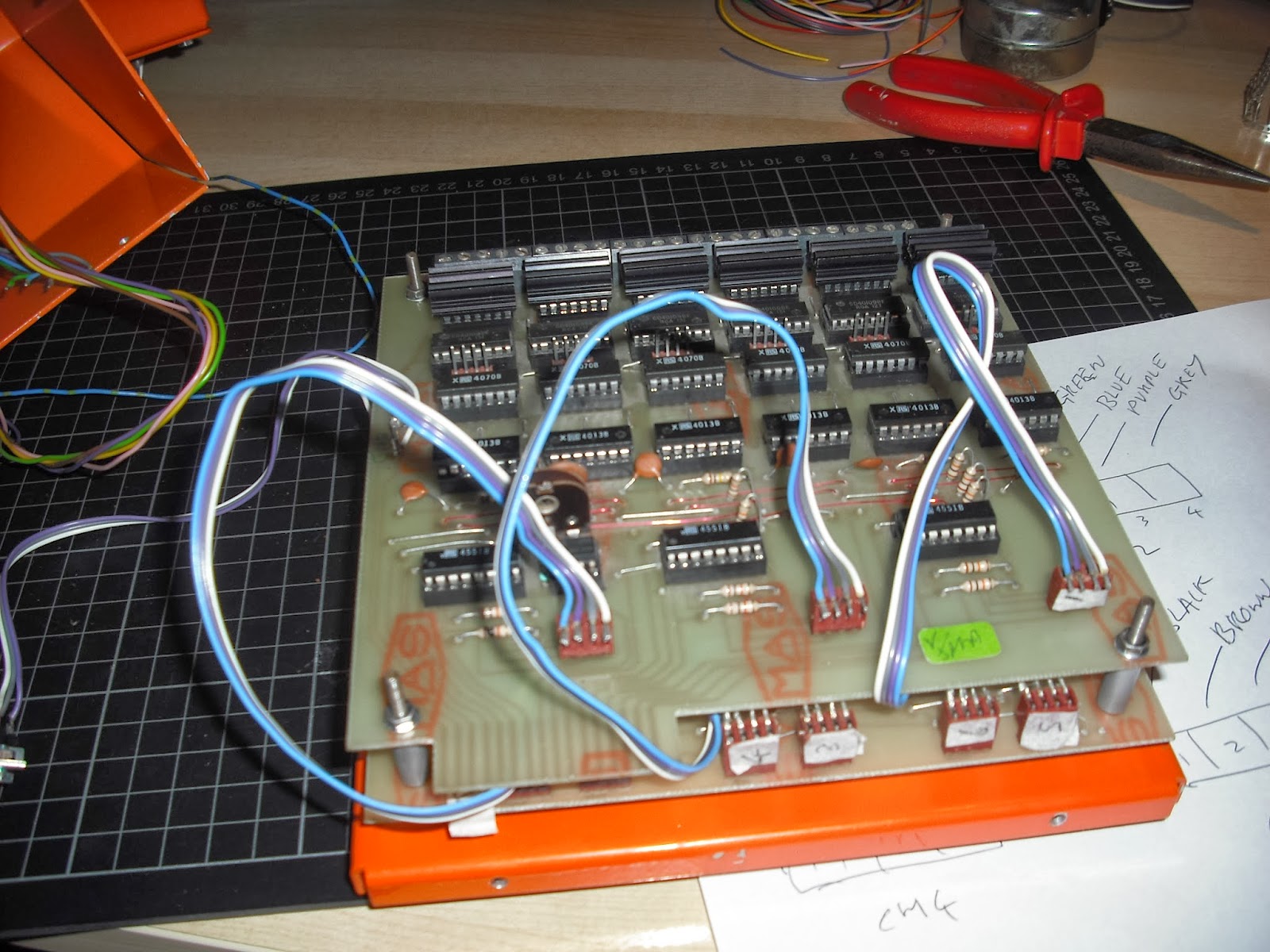
The micro-switch sensors feed into the lower interface board, so, before removing anything else, I separated the two boards and disconnect them.  I  completely removed the wiring loom, as I'm currently not making any use of it.

Finally, the prototype interface board is freed:


In order to connect the steppers to the new interface board, I soldered up connectors (see Testing a Stepper Motor for wiring details) and inserted in no particular order for testing purposes:


The heat-shrinking annoyed Yulia.  She'd been waiting all morning to wash her hair, and I was busy using the hairdryer !

Final bench test of the new interface board:


All motors were tested independently using the Arduino controller.  Eventually, I started issuing commands to drive multiple motors, and in different directions.  I carefully tested the base motor ensuring I wasn't tearing any cables!

 A short video showing 5 motor channels spinning simultaneously:


There is no need to worry about the alignment of the timing belts when testing the Armdroid this way - the 108T reduction gears would normally prevent excessive movement of gearing on the drive shaft.

Believe it or not, I managed to spin all 5 motors over 100RPM.  I will be doing further research driving motors at higher speeds, but I will need to rewrite my Arduino software at a lower-level to get major performance improvements.   Of course, higher speeds results in reduced torque, a side-effect of stepper motors.

I do however have some "clunks" happening at regular intervals.  This might be a consequence of the fractured pulleys, as I now have replacements, I will replace these and see if this makes any difference.

Saturday, 22 February 2014

Interface Bench Test - Part 4

This morning, I decided instead of using HyperTerminal, or the Ardunio IDE Serial Monitor to interact with the Armdroid, I thought it would be good idea to develop a dedicated Windows application:


This is a fairly simple test application, but it should be good enough for anybody to test their Armdroid from any Windows based PC using Serial/USB connectivity.   I think you'll agree, this is a lot more user-friendly than what was shown in my last update.

You have to select which port your Armdroid is connected too.  Once connected, you can choose the motor channel, and step the motor any number of times:


Feedback from the controller is displayed in the output panel :


The application was developed in Visual Studio 2012 using the Microsoft .NET Framework.

Later, I'll be publishing my Armdroid Control Protocol specification Version 1.0, just as soon as I've finished my initial development work.

I'm going to standardize all my development activities around this protocol, and by doing so, we can have IBM PCs talking to Arduino or Raspberry Pi hosted Armdroid controllers, and more....   This platform independence will allow us to support many combinations of hosts/controllers in future.   Hopefully other readers/developers might adopt the same standard, and we'll see more Armdroid applications appear in time.

This can be downloaded from the software section - Windows Tools

Thursday, 20 February 2014

Interface Bench Test - Part 3

I thought it would be a good idea to check through my program code on paper, checking the stepper motor sequencing is ready, and guess what....   I discovered a few bugs design limitations which had to be resolved before commencing the test.


To confirm the Arduino/Armdroid interface wiring used, the following connections have been made:

ARDUINO PIN
FUNCTION
ARMDROID PIN
2
D1
4
3
D2
3
4
D3
6
5
D4
5
6
D5
8
7
D6
7
8
D7
10
9
D8
9

The common grounds have been connected together - that's Pin 2 on the Armdroid interface, connected to any of the Ardunio's GND power pins.


Normally, I have some good news, and bad news.....  But, in this case, it's only good news to report....

The interface board is working faultlessly.

Motor addressing worked as expected for this generation of interface board.   I checked every motor channel, making sure the motor spins clockwise/counter-clockwise.   I also made certain that selecting a motor channel, doesn't inadvertently activate another motor channel.  I couldn't actually be happier with the results of my bench test!


If your wondering how this was done....   In my last post, I mentioned the Ardunio will be responding to commands sent via the Serial Port.   I have designed a simple communications protocol, which is the backbone to this.

The following functions have currently been implemented:
  • Select a motor channel
  • Drive a motor with a specified number of steps
  • Set the motor speed in RPM
  • Write a value directly to the Armdroid interface port


This is a screen shot of the Serial Monitor showing the waveform outputs (in binary) in use when pulsing the stepper motor on channel six :


This level of tracing proved to be invaluable for diagnosing a few other issues in the software.   This certainly helps to visualize whats happening on the Armdroid interface.

I intend to develop this protocol further to support driving multiple motors (necessary for pitching/rolling the gripper) and tracking motor offsets counters which can be used to return the arm to a predefined home position.


The source code will be published shortly.   I'm currently moving all my source code into a new GitHub Repository, so please check back later.....

Saturday, 15 February 2014

Interface Bench Test - Part 2

I should have titled this Déjà vu

Last night turned into a fairly intensive evening of tracing the entire interface circuitry....  I did this not once, but twice!


I started by tracing the pinouts of the interface cable, confirming these match the literature, and what has been document elsewhere on the internet.

One problem I've found with the original documentation, it's not very clear illustrating these pin assignments, so I've put together the following table which might help:


PIN
ARMDROID FUNCTION
INPUT BITS
OUTPUT BITS
1
+5 V


2
GND


3
D2
N/C
A1
4
D1 (STROBE)
HIGH
LOW
5
D4
MS2
A3
6
D3
MS1
A2
7
D6
MS4
D2
8
D5
MS3
D1
9
D8
MS6
D4
10
D7
MS5
D3


The physical wiring is very different to prototype models.
At this point, I wanted to double check the address decoding of motor selections.

This has been the subject of great confusion, not only to myself, but other readers too.   My prototype variant turned out to have A1 as the most significant address bit, not A3 as expected.   It  seemed odd why this was the case, and without finding any examples of source code on the internet, it turned into one of those little mysteries of life.

Tracing this part of the circuit however resulted in a bit of a discovery....

Address bits A3 and A1 have been swapped, which means the address decoding for this generation of interface board is completely different to prototype variants.

My tracing determined:
D2 (exiting pin 8 from IC2C) feeds into Pin 1 (A) of the Demultiplexer (74LS138 / IC6)
D3 (exiting pin 6 from IC2B) feeds into Pin 2 (B)                  "
D4 (exiting pin 3 from IC2A) feeds into Pin 3 (C)                  "

Hopefully, any reader who previously read my post "Motor Addressing Solved" will understand that only applies to the address decoding of prototype variants only.   I would imagine, all later generations follow the above form of addressing logic.

I wonder if Colne made a mistake in the PCB routing of early prototype models, and subsequently corrected things?

To complicate matters, some of the schematics contain minor mistakes.  In time, I will redraw these for both generations of circuit boards, and make them available on this site.

I've previously spoken about my intention to develop a software library, and of course, this will need to support both addressing modes.   From a higher level view, any software consuming this library need not actually be concerned with these implementation details, we just need to config it correctly, and the library will do all the hard work.


Anyway, with the pinouts confirmed, I am now wiring up my Arduino with a higher degree of confidence something might actually work:


Output pins 2 - 9 have been wired to correspond to bits D1 - D8, and the switching is all done in hardware.  This keeps things logically consistent with my existing Raspberry Pi interface, and that means program code should port relatively easily between the two devices.

Pins 0 (RX) and 1 (TX) have purposely been left unconnected, this is necessary when using serial communication.   My test program will be responding to commands sent via USB/Serial, this is why I have chosen to use the above pin assignments.

The +5 V line is not used, and common grounds have been connected together.  The Arduino Leonardo is a native 5V device, therefore no voltage conversion is necessary.

I'm currently making final edits to my program code, and then we're ready for the ultimate test this weekend....

Thursday, 6 February 2014

Driver Testing

In my previous post, we tested a stepper motor by manually pulsing the motor coils, and that was all basic stuff.

Shortly afterwards, it occurred to me, building a test circuit around the ULN2003A Darlington Driver wouldn't be such a bad idea.   I could use this circuit to verify each of the four ULN2003 drivers (IC13 - IC16) from my interface board.  You could also use this to test a driver and stepper in one!

By replacing any faulty driver chips, we should then be in a position knowing everything on the High Current side of the interface circuit is good.

The following test circuit uses an Arduino to sequence the motor steps, and has also been designed around Colne Robotics stepper motor wiring:


Notice how two inputs are exchanged - this is necessary to make the Arduino Stepper Library compatible with the Armdroid's stepper motor wiring (see previous posting); otherwise the pulse sequences will be wrong, the motor will not rotate.

I've previously talked about the hardware switching of two lines Qb and Qc, this is easily illustrated looking at the outputs of the ULN2003 and how they map to stepper motor coil inputs A + C and B + D

OUT1 = Qd
OUT2 = Qb
OUT3 = Qc
OUT4 = Qa

You can compare in contrast to the more regular wiring of unipolar steppers (see Arduino example circuits) where the wiring sequence is more sequential.

Further clarification can be found in the circuit diagram/construction notes.
I really have no explanation why Colne Robotics choose this wiring arrangement.


The accompanying sketch continually rotates the motor in alternating directions - this is good enough to spot any motion irregularities:

 /*  
  * ID35 Stepper Sketch  
  * http://armdroid1.blogspot.co.uk  
  */  
   
 #include "Stepper.h"

 #define ID35_STEPS 48  
 Stepper id35_stepper(ID35_STEPS, 2, 3, 4, 5);  
   
 void setup()  
 {  
   id35_stepper.setSpeed(20); // RPMs  
 }  
   
 void loop()   
 {  
   // rotate clockwise  
   id35_stepper.step(ID35_STEPS);  
   delay(500);  
   
   // rotate counter-clockwise   
   id35_stepper.step(-ID35_STEPS);  
   delay(500);  
 }  
sketch_ID35_stepper.ino


The circuit was first tested with a new ULN2003A driver from my parts box.  After making sure everything was running smoothly, I removed each of the four darlingtons from my interface board, and fitted them, one at a time into the test circuit above.


Driver (IC16) extraction from Armdroid interface PCB


But, we're not done just yet....   The ULN2003A supports 7 channels of current amplification (IN1 - IN7), three of the ULN2003 (ICs 13 - 15) fitted to the Armdroid's interface use all seven of these channels.   To test these additional channels, simply re-wire the inputs to use IN4 - IN7 and likewise with the corresponding outputs to be OUT4 - OUT7, nothing else needs to change!

Re-arranged wiring to test IN4 - IN7

All of my darlingtons turned out to be good.  But, it's well worth checking these, as these are probably the components most likely to fail on a circuit of this age.

The two darlingtons replaced by ECG2013 equivalents - I hadn't heard of these chips before, but double checking a datasheet found on the internet indicates they have exactly the same ratings as the ULN2003 they replace.  Both are rated with an output current of 500 mA and maximum voltage 50 V.

I've added both datasheets to the resources section.


My next post will concentrate on final preparations for bench testing the interface board....