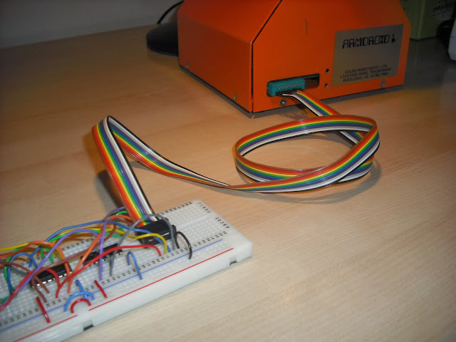
Here's how this was assembled.....
Firstly, solder up the 10-way ribbon cable to a 20-way card edge connector - we only need to use one side as follows:
The other end is terminated with a 2x5 ribbon crimped connector:
To crimp, you need plenty of pressure... But, you don't want to damage the pins in doing so....
I sacrificed an IC socket by removing the pins, inserted the crimp connector into the shell of this IC socket which protects the pins, inserted the ribbon cable, and pushed together using a clamp like this....
A small G-style Clamp would also do the trick, except I couldn't find one in my garage!
Now, we're ready to install onto the interface circuit:
Minor wiring rearrangements made to route correct cables through to the ribbon cable. I have also coupled up the ground line (black) to the ground power rail on the breadboard. The +5volts (white) power line from the Armdroid is left unconnected:
You'll notice that when I constructed the circuit last week, I adopted the colour coding of my wiring based on the ribbon cable, which should simplify troubleshooting.
Finally, one last check with the multimeter checking we're not dropping resistance, and verify continuity. Then tested the whole circuit again with the Digital Logic Probe:
The completed interface:


No comments:
Post a Comment