I wanted to swap the interface driver boards, unfortunately this wasn't so simple, and required delicate key hole surgery.

The challenge was removing the awkward cable tie securing the wiring inside the bearing assembly. You can just about make this out in the pictures below:
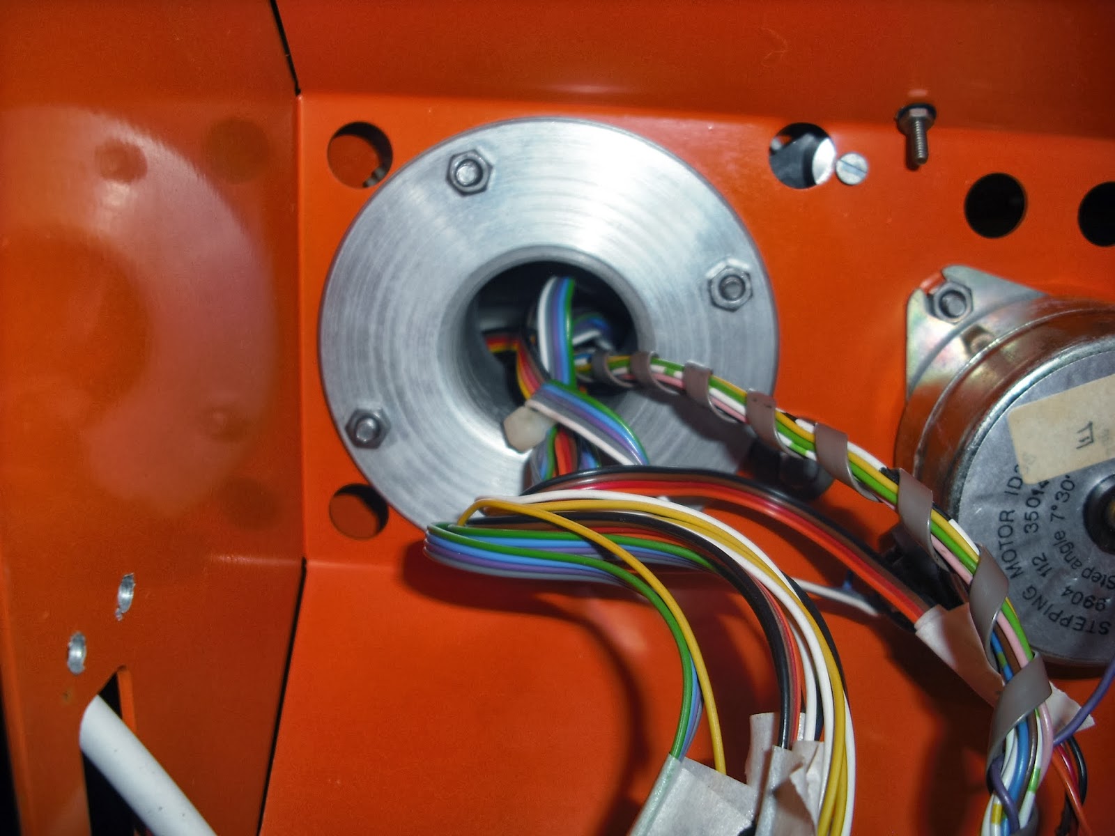

The power connections made by soldering directly to the board had to be removed, along with the 7805 power regulator bolted to the chassis.
Next, the stepper motor wiring was disconnected. These terminal blocks are over 30 years old, needless to say, most of the terminals had rusted/seized solid.
The following table shows the stepper motor connections for this type of interface - included for my own reference:
TERMINAL
|
FUNCTION
|
CHANNEL #
|
RIBBON
CABLE
|
1
|
+12
V
|
YELLOW
/ WHITE
|
|
2
|
Qa
|
1
|
BLACK
|
3
|
Qc
|
1
|
BROWN
|
4
|
Qb
|
1
|
RED
|
5
|
Qd
|
1
|
ORANGE
|
6
|
Qa
|
2
|
GREEN
|
7
|
Qc
|
2
|
BLUE
|
8
|
Qb
|
2
|
PURPLE
|
9
|
Qd
|
2
|
GREY
|
10
|
Qa
|
3
|
GREEN
|
11
|
Qc
|
3
|
BLUE
|
12
|
Qb
|
3
|
PURPLE
|
13
|
Qd
|
3
|
GREY
|
14
|
Qa
|
4
|
BLACK
|
15
|
Qc
|
4
|
BROWN
|
16
|
Qb
|
4
|
RED
|
17
|
Qd
|
4
|
ORANGE
|
18
|
Qa
|
5
|
BLACK
|
19
|
Qc
|
5
|
BROWN
|
20
|
Qb
|
5
|
RED
|
21
|
Qd
|
5
|
ORANGE
|
22
|
Qa
|
6
|
GREEN
|
23
|
Qc
|
6
|
BLUE
|
24
|
Qb
|
6
|
PURPLE
|
25
|
Qd
|
6
|
GREY
|
The micro-switch sensors feed into the lower interface board, so, before removing anything else, I separated the two boards and disconnect them. I completely removed the wiring loom, as I'm currently not making any use of it.
Finally, the prototype interface board is freed:
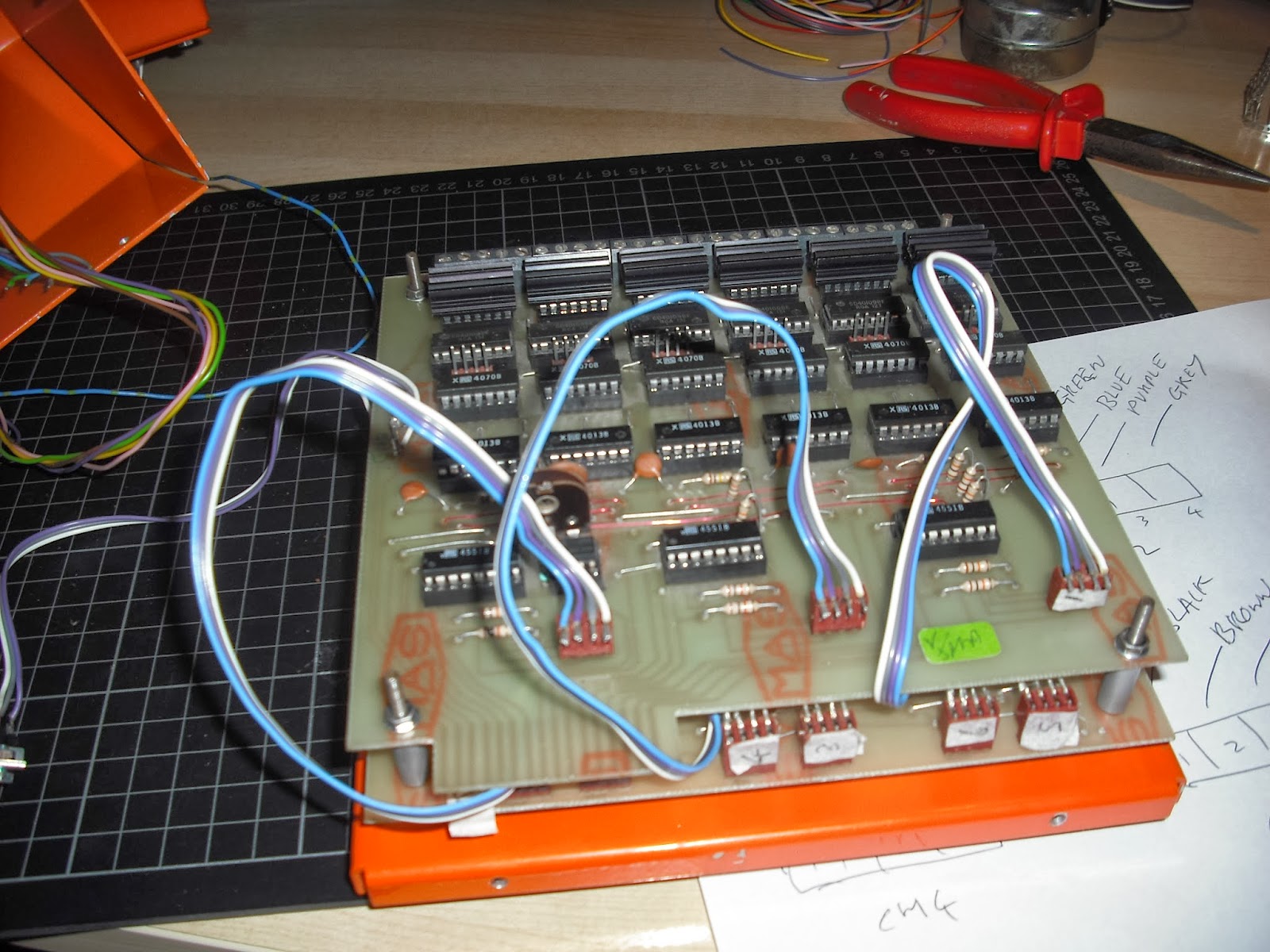
In order to connect the steppers to the new interface board, I soldered up connectors (see Testing a Stepper Motor for wiring details) and inserted in no particular order for testing purposes:

The heat-shrinking annoyed Yulia. She'd been waiting all morning to wash her hair, and I was busy using the hairdryer !
Final bench test of the new interface board:


All motors were tested independently using the Arduino controller. Eventually, I started issuing commands to drive multiple motors, and in different directions. I carefully tested the base motor ensuring I wasn't tearing any cables!
A short video showing 5 motor channels spinning simultaneously:
There is no need to worry about the alignment of the timing belts when testing the Armdroid this way - the 108T reduction gears would normally prevent excessive movement of gearing on the drive shaft.
Believe it or not, I managed to spin all 5 motors over 100RPM. I will be doing further research driving motors at higher speeds, but I will need to rewrite my Arduino software at a lower-level to get major performance improvements. Of course, higher speeds results in reduced torque, a side-effect of stepper motors.
I do however have some "clunks" happening at regular intervals. This might be a consequence of the fractured pulleys, as I now have replacements, I will replace these and see if this makes any difference.
No comments:
Post a Comment